Golf club head

a golf club and head technology, applied in the field can solve the problems of increased head weight, and large volume of golf club head, and achieve the effects of high hitting sound, good hitting sound, and excessive lowering of hitting sound

Inactive Publication Date: 2011-08-02
SUMITOMO RUBBER IND LTD
View PDF26 Cites 155 Cited by
  • Summary
  • Abstract
  • Description
  • Claims
  • Application Information

AI Technical Summary

Benefits of technology

[0008]The hollow golf club head with a great volume has a drawback that a hitting sound is excessively lowered. A higher hitting sound is preferable in order to obtain a good hitting sound. When the rib is provided on the inner surface of the sole, the rigidity of the sole increases and the hitting sound is high. However, in this case, the increase in the weight of the head is caused by the existence of the rib.
[0009]It is possible to form a groove on an outer surface of the sole and to form a protruding part at a position on the reverse side of the groove on the inner surface of the sole. The constitution can suppress the increase in the weight and enhance the rigidity of the sole. The enhancement of the rigidity of the sole can improve the hitting sound. However, in this case, stress concentrates on the groove or the protruding part on the reverse side thereof, and the durability is apt to be deteriorated.
[0010]It is an object of the present invention to provide a golf club head capable of attaining the improvement of the hitting sound and the enhancement of the durability while suppressing the increase in the weight.

Problems solved by technology

The hollow golf club head with a great volume has a drawback that a hitting sound is excessively lowered.
However, in this case, the increase in the weight of the head is caused by the existence of the rib.
However, in this case, stress concentrates on the groove or the protruding part on the reverse side thereof, and the durability is apt to be deteriorated.

Method used


Image

  • Golf club head
  • Golf club head
  • Golf club head

Examples


example 1

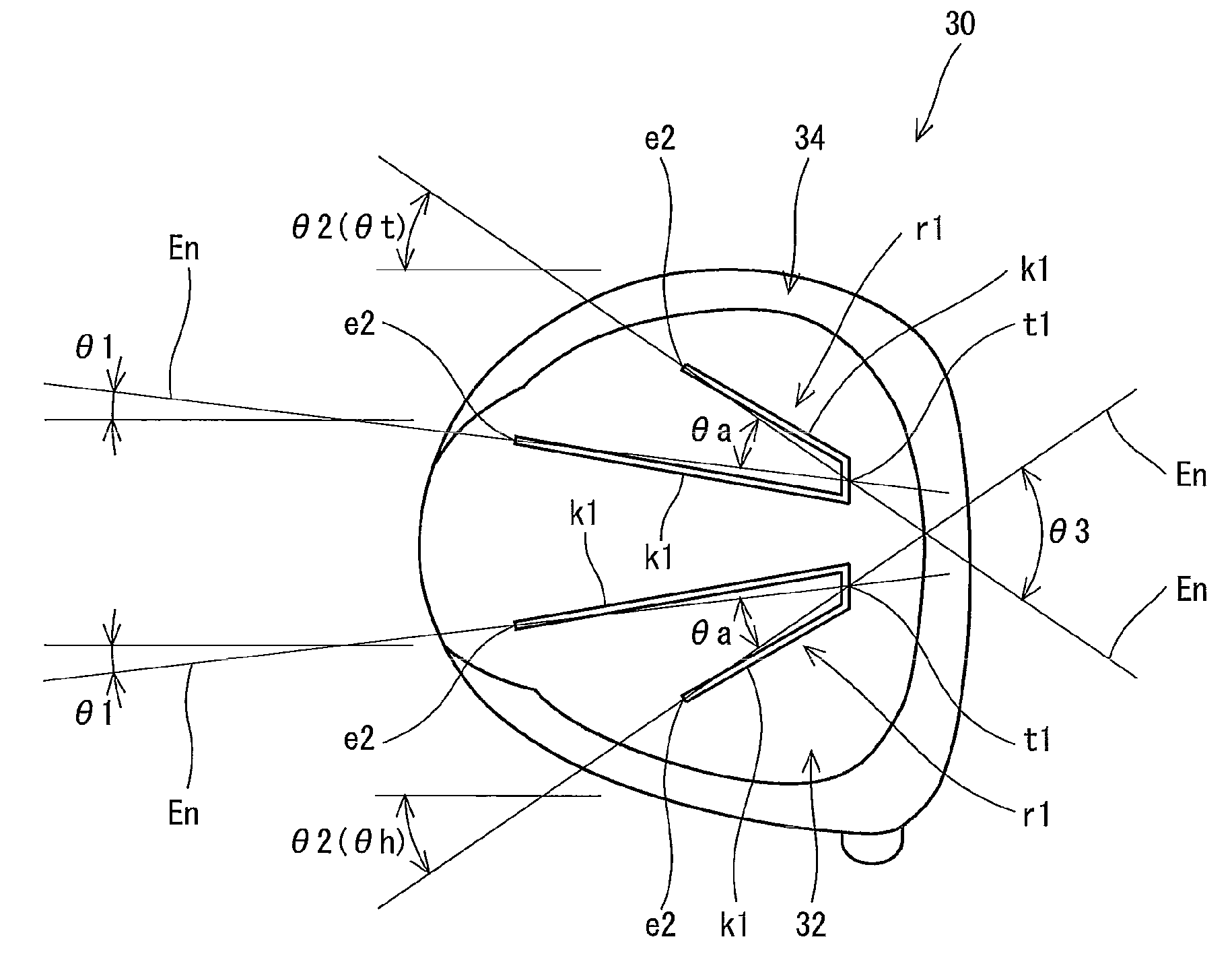
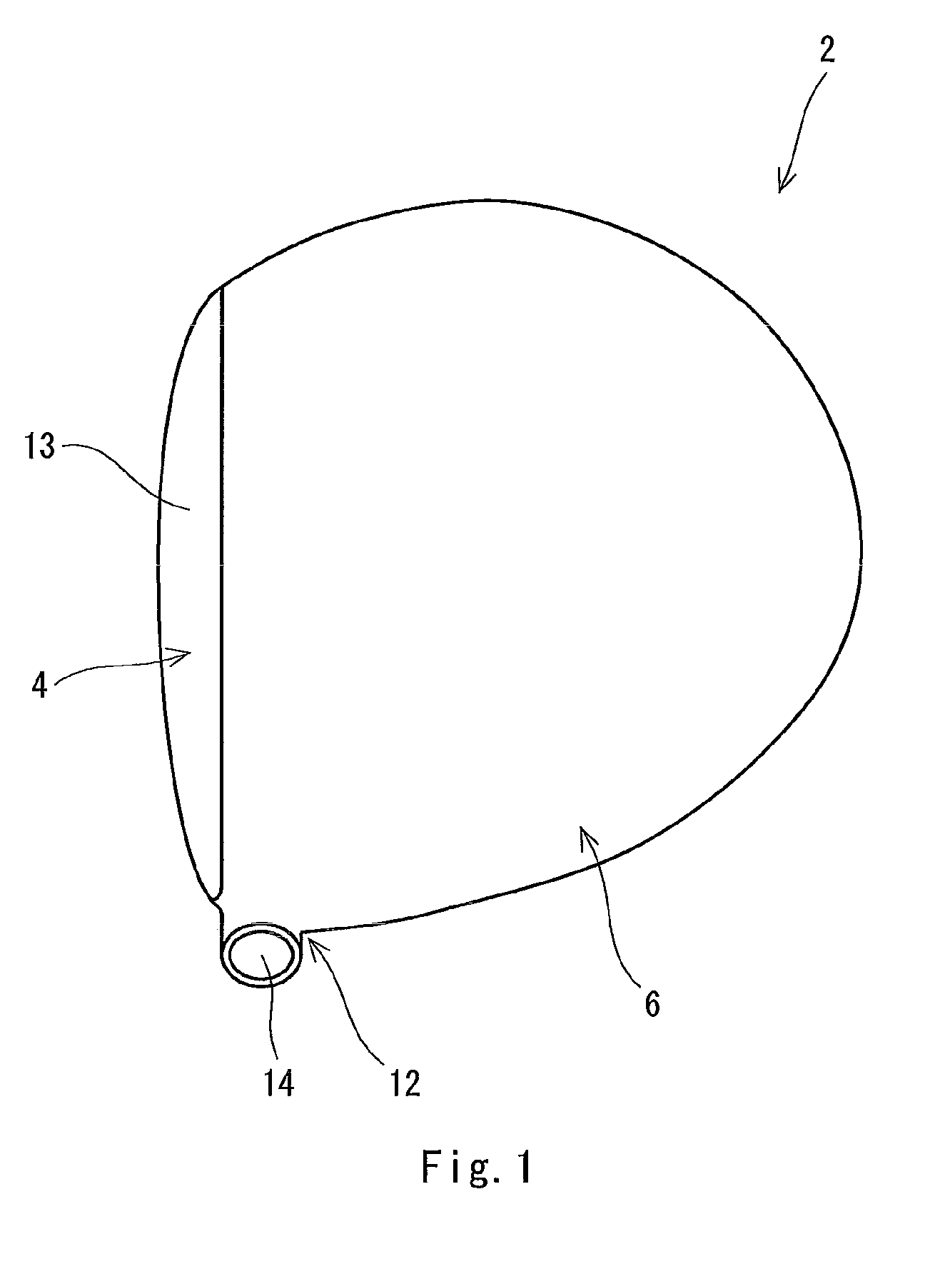
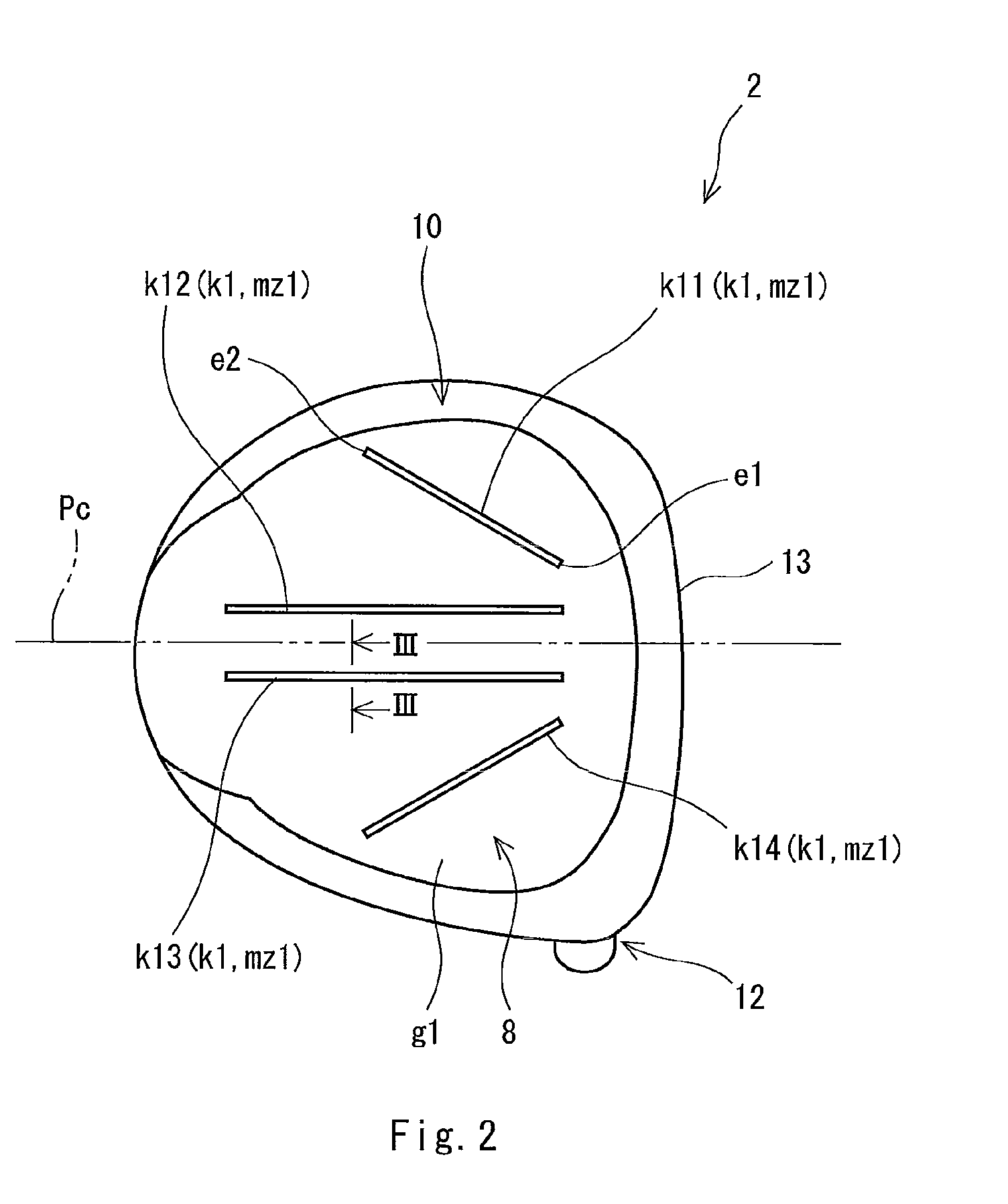
[0128]A head having the same structure as that of the head 2 was produced. The configuration of a groove forming part as shown in FIG. 2 was used. A head body was obtained by subjecting a titanium alloy (Ti-6Al-4V) to lost-wax precision casting. A face member was obtained by forging a titanium alloy (Ti-15V-3Cr-3Sn-3Al). The head body and the face member were welded, and the outer surface of the head was ground to obtain the head. The volume of the head was 460 cc. The weight of the head was 185 g.

[0129]An angle θa formed by two groove forming parts located on a toe side relative to a center section plane Pc was set to 30 degrees. An angle θa formed by two groove forming parts located on a heel side relative to the center section plane Pc was set to 30 degrees. Both angles θ1 of two positions were set to 0 degree. Both angles θ2 of two positions were set to 30 degrees. A shaft and a grip were mounted to the head to obtain a golf club according to Example 1. The specifications and ev...

example 2

[0130]A head and a golf club according to Example 2 were obtained in the same manner as in Example 1 except that the configuration of a groove forming part as shown in FIGS. 5 and 6 was used and that the weight of a head was set to 187 g. The specifications and evaluation results of Example 2 are shown in the following Table 1.

[0131]In Example 2, an angle θa formed by two groove forming parts located on a toe side relative to a center section plane Pc was set to 30 degrees. An angle θa formed by two groove forming parts located on a heel side relative to the center section plane Pc was also set to 30 degrees. Both angles θ1 of two positions were set to −5 degrees. Both angles θ2 of two positions were set to 25 degrees.

example 3

[0132]A head and a golf club according to Example 3 were obtained in the same manner as in Example 1 except that the configuration of a groove forming part as shown in FIGS. 7 and 8 was used and that the weight of a head was set to 187 g. The specifications and evaluation results of Example 3 are shown in the following Table 1.

[0133]In Example 3, an angle θa formed by two groove forming parts located on a toe side relative to a center section plane Pc was set to 20 degrees. An angle θa formed by two groove forming parts located on a heel side relative to the center section plane Pc was also set to 20 degrees. Both angles θ1 of two positions were set to 10 degrees. Both angles θ2 of two positions were set to 30 degrees.


PUM


Abstract

A head 2 is hollow. The head 2 has a sole part 8. The sole part 8 has a groove forming part k1 having a recessed outer surface g1 and a protruding inner surface s1. The sole part 8 has a first groove forming part k1 and a second groove forming part k1. The first groove forming part k1 and the second groove forming part k1 have a front-back directional length. A distance between the first groove forming part k1 and the second groove forming part k1 in a toe-heel direction is wider toward a back of the head. Preferably, the first groove forming part k1 and the second groove forming part k1 exist on a back of a face surface 13. Preferably, the sole part 8 has a connecting groove part r1. The connecting groove part r1 is formed by connecting a front end of the first groove forming part k1 to a front end of the second groove forming part k1 with each other.

Description

[0001]The present application claims priorities on Japanese Patent Application No. 2008-197587 filed on Jul. 31, 2008. The whole contents of the Japanese Patent Application are hereby incorporated by reference.BACKGROUND OF THE INVENTION[0002]1. Field of the Invention[0003]The present invention relates to a hollow golf club head.[0004]2. Description of the Related Art[0005]A hollow golf club head has been known. The hollow structure increases a head volume and a moment of inertia. A so-called wood type golf club head is usually hollow.[0006]The volume of a hollow part is increased and the thickness of the head is thinned with the increase in size of the head. The head increased in size causes a loud hitting sound.[0007]Golf club heads for obtaining a good hitting sound have been disclosed. As the inventions considering a hitting sound, Japanese Unexamined Patent Application Publication No. 2006-204604 (US2006-172818 A1), Japanese Unexamined Patent Application Publication No. 2008-86...

Claims


Application Information

Patent Timeline
Patent Type & Authority Patents(United States)
IPC IPC(8): A63B53/04A63B102/32
CPCA63B53/0466A63B49/06A63B2053/0433A63B2071/0625A63B2053/0408A63B2209/00A63B2209/02A63B53/047A63B60/52A63B53/0408A63B53/0433
Inventor ABE, HIROSHI
Owner SUMITOMO RUBBER IND LTD
Why Eureka
Try Eureka