Quasi-spherical orbital implant

a quasi-spherical, implant technology, applied in the field of eye replacement implants, can solve the problems of more difficult for the prosthesis to undesiredly rotate in the orbit, and achieve the effects of improving the motility improving the grip of the implant, and improving the mobility of the prosthetic ey

Active Publication Date: 2011-08-02
OCULO PLASTIK
View PDF15 Cites 4 Cited by
  • Summary
  • Abstract
  • Description
  • Claims
  • Application Information

AI Technical Summary

Benefits of technology

[0010]The present invention is a generally smooth surfaced ocular implant device with a quasi-spherical shape. The implant is a quasi-sphere (not a true sphere) because it has an elongated posterior end and an astigmatism with added details anteriorly. The posterior end of the implant is conically elongated off-center, toward the medial side of the implant. The conical elongation helps to keep the entire implant properly aligned because it mimics the natural shape of the bony orbit of the human eye which extends inward (toward the brain), and medially (toward the nasal passage).
[0011]The anterior portion of the implant is astigmatic because the medial and temporal portions are bulkier than the superior and inferior portions. The astigmatism makes it more difficult for the prosthesis to undesirably rotate in the orbit. The bulkier medial and temporal portions of the implant stabilize the prosthesis because the astigmatic shape allows the implant to make better contact (key) with the prosthesis than would a spherical implant.
[0013]The anterior portion of the implant has a number of mounds and valleys. The mounds protrude away from the surface of the quasi-spherical implant so as to key with the prosthetic eye and provide improved motility of the prosthetic eye. The valleys provide an area into which the eye muscles and tissue can be placed so they can better grip the implant during muscle movement, which also improves motility.

Problems solved by technology

The astigmatism makes it more difficult for the prosthesis to undesirably rotate in the orbit.

Method used


Image

  • Quasi-spherical orbital implant
  • Quasi-spherical orbital implant
  • Quasi-spherical orbital implant

Examples


first preferred embodiment

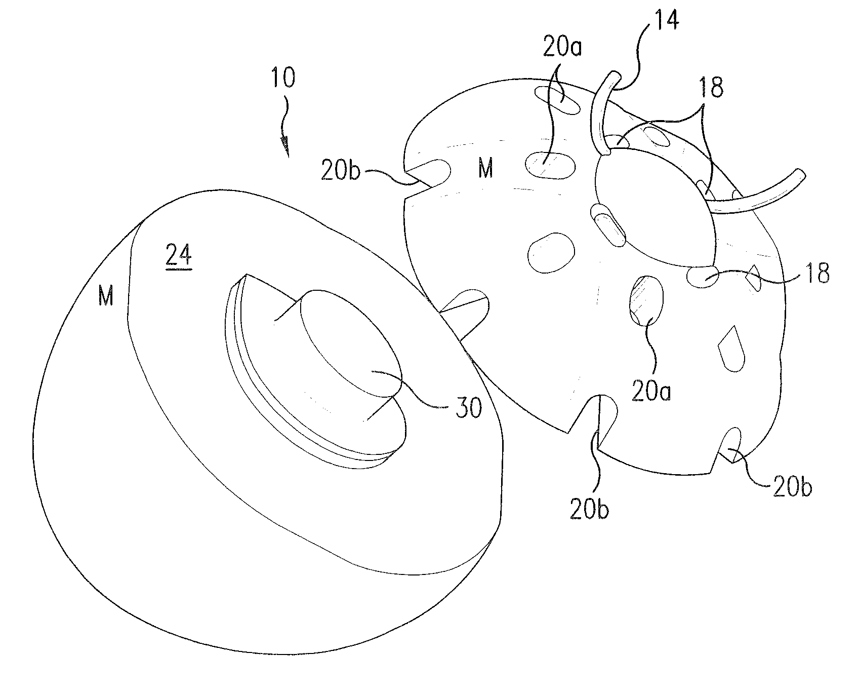
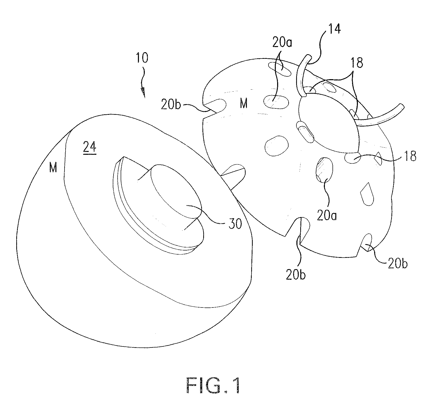
[0044]FIGS. 1 and 5-8 show a first preferred embodiment of the present invention which comprises all the general features described above in addition to the specific features described below. The first preferred embodiment is comprised of a polymer such as acrylic. As described above, the implant 10 is preferably manufactured in two pieces 22, 24. The two pieces 22, 24 are then combined by any suitable means. The preferred means of assembling the two pieces 22, 24 for the acrylic implant 10 is ultra-sonic welding, which is known in the art. As shown in FIGS. 1 and 7, there is an elevated portion 30 on the surface of the posterior portion 24. This elevated portion 30 is adapted for insertion into a correspondingly shaped indentation (not shown) on the underside of the anterior portion 22. The elevated portion 30 is preferably semi-elliptical; however it can be any shape as long as the two portions 22, 24 can only fit together when the portions 22, 24 are orientated in their proper po...

second preferred embodiment

[0047]FIGS. 9-12 and 12a show a second preferred embodiment of the present invention which comprises all of the general features of the invention described above in addition to the features described below. The second preferred embodiment is comprised of a biomaterial that is elastomeric or an elastomer polymer such as silicone. In this embodiment, the anterior portion 22 and posterior portion 24 are adapted to be snapped together, since silicone cannot be welded. The preferred means for combining the two pieces in this embodiment is shown in FIGS. 12 and 12a, wherein tentacles 26 that are attached to the anterior portion 22 are placed through corresponding openings 25 in the posterior portion 24. The tentacles 26 have an enlarged portion 27 which cannot easily be removed from the openings 25 after being inserted into the openings 25. Once inserted into the openings 25, the enlarged portions 27 lock or snap the two portions 22, 24 together. Preferably there are two tentacles 26 so t...

third preferred embodiment

[0050]FIG. 14 shows a third preferred embodiment of the implant 10 of the present invention wherein the valleys 11 and mounds 12 are more pronounced than in the first two embodiments. This embodiment can be manufactured with the characteristics of either the first or the second embodiment, with the only difference being the increased definition of the valleys 11 and mounds 12 on the anterior portion 22. The third preferred embodiment is still a quasi-sphere, however, the larger valleys 11 and mounds 12 help to increase the keying of the implant 10 on the ocular prosthesis for more motility and reduce the potential for rotation of the ocular prosthesis. The third preferred embodiment does not have an astigmatism in the anterior portion 22 because of the more pronounced valleys 11 and mounds 12. The third embodiment is not as likely to work well with stock prosthesis because of the more pronounced valleys 11 and mounds 12.


PUM


Abstract

A quasi-spherical orbital implant that comprises an off center conical elongation toward its posterior and medial aspects. The conical elongation mimics the natural shape of an orbit. The implant comprises a number of holes and tunnels for suturing the patient's eye muscles and tissue to the implant. A number of hollow voids in the implant serve to progressively host the formation of tissue which secures the implant to the muscles and covering tissue and helps to prevent migration after the sutures have dissolved. The anterior portion of the implant has a number of details which key with the prosthetic eye and help improve its stability and motility.

Description

BACKGROUND OF THE INVENTION[0001]The invention relates to eye replacement implants. If an eye has become damaged due to trauma or disease, the damaged eye may have to be eviscerated in which all of the inner contents of the eye are removed, or an enucleation may be performed in which the entire eyeball is removed after severing it from the eye muscles and the optic nerve. Following either of these procedures, it is common practice to fill the resulting void with an orbital implant and subsequently fit an ocular prosthesis that closely resembles the eye. After the implant has been inserted into the eye socket following enucleation or evisceration of the eye, tissues heal over the implant. The ocular prosthesis is then placed over these tissues that have healed over the implant. When properly placed within the orbit, the orbital implant replaces some of the volume lost when the eye was removed and helps to maintain the normal structure of the eyelids and eyebrows. When the ocular pros...

Claims


Application Information

Patent Timeline
Patent Type & Authority Patents(United States)
IPC IPC(8): A61F2/16
CPCA61F2/141
Inventor DURETTE, JEAN-FRANCIOS
Owner OCULO PLASTIK
Why Eureka
Try Eureka