Driver circuit for producing signal simulating transmission loss

a technology of transmission loss and driver circuit, applied in the direction of pulse technique, computer operation for integration/differentiation, instruments, etc., can solve the problem of loss of high frequency component of signal

Inactive Publication Date: 2011-08-02
ADVANTEST CORP
View PDF14 Cites 3 Cited by
  • Summary
  • Abstract
  • Description
  • Claims
  • Application Information

AI Technical Summary

Benefits of technology

[0015]The driver circuit according to the present invention for outputting a simulated signal simulating the transmission loss, the driver circuit comprises: a main driver which receives the input signal and outputs a first signal corresponding to the input signal; a sub driver which receives the input signal and outputs a second signal by inverting the input signal; a high frequency emphasizing circuit which receives the second signal and outputs a third signal having the high frequency of the second signal emphasized; and an addition unit which outputs the simulated signal by adding the first signal and the third signal, whereby a signal simulating a signal subjected to transmission loss can be generated without the need of a complicated circuit structure.

Problems solved by technology

Usually, the transmission line has integration characteristics, and thus, the high frequency component of a signal is lost.

Method used


Image

  • Driver circuit for producing signal simulating transmission loss
  • Driver circuit for producing signal simulating transmission loss
  • Driver circuit for producing signal simulating transmission loss

Examples


first embodiment

[0125]The driver circuit according to a first embodiment of the present invention will be explained with reference to FIGS. 3 to 5. FIG. 3 is a block diagram showing a structure of the driver circuit according to the present embodiment. FIG. 4 shows the waveforms of signals at respective points of the driver circuit according to the present embodiment. FIG. 5 is a circuit diagram showing a structure of the driver circuit according to the present embodiment.

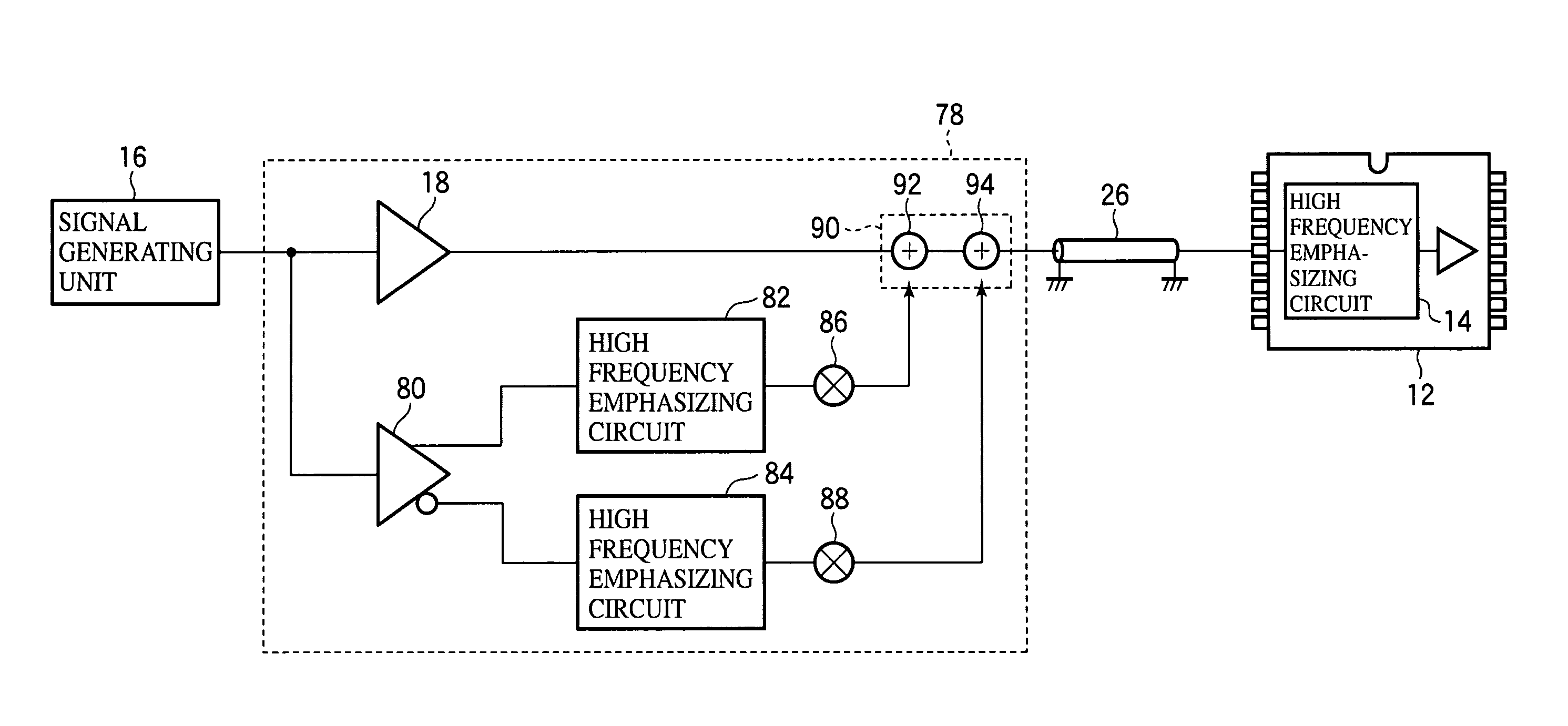
[0126]The driver circuit 10 according to the present embodiment is a driver circuit incorporated in a semiconductor test device for testing the high frequency emphasizing circuit 14 incorporated in a DUT 12 to compensate a transmission loss, and receives an input signal from the signal generating unit 16, generates a simulated signal simulating a signal subjected to a transmission loss and supplies the simulated signal to the DUT 12.

[0127]As illustrated in FIG. 3, the driver circuit 10 according to the present embodiment comprises...

second embodiment

[0150]The drive circuit according to a second embodiment of the present invention will be explained with reference to FIG. 6 which is a block diagram showing a structure of the driver circuit according to the present embodiment. The same members of the present embodiment as those of the driver circuit according to the first embodiment are represented by the same reference numbers.

[0151]The driver circuit 62 according to the present embodiment includes an amplification circuit 64 for amplifying an output signal outputted from the addition circuit 24 in addition to the structure of the driver circuit 10 according to the first embodiment illustrated in FIG. 3.

[0152]As illustrated in FIG. 6, the amplification circuit 64 of the driver circuit 62 according to the present embodiment receives an input signal from the addition circuit 24 and outputs a signal by amplifying the input signal. The output signal of the amplification circuit 64 is supplied to a DUT 12 via the loss-free transmissio...

third embodiment

[0154]The driver circuit according to a third embodiment of the present invention will be explained with reference to FIGS. 7 to 10. FIG. 7 is a block diagram showing a structure of the driver circuit according to the present embodiment. FIGS. 8 and 9 show waveforms of signals at respective points of the driver circuit according to the present embodiment. FIG. 10 is a circuit diagram showing an example of circuit structure of the driver circuit according to the present embodiment. The same members of the present embodiment as those of the driver circuit according to the first and the second embodiments are represented by the same reference numbers.

[0155]The driver circuit 66 according to the present embodiment further includes a multiplication circuit 68 for correcting the amplitude of an output signal of the high frequency emphasizing circuit 22 by multiplying the output signal of the high frequency emphasizing circuit 22 with a prescribed correction value in addition to the struct...


PUM


Abstract

In a driver circuit 10 for outputting a simulated signal simulating an input signal subjected to transmission loss, corresponding to the input signal, the driver circuit 10 comprises: a main driver 18 which receives the input signal and outputs an output signal corresponding to the input signal; a sub driver 20 which receives the input signal and outputs an output signal given by inverting the input signal; a high frequency emphasizing circuit 22 which receives the input signal of the sub driver 20 and outputs an output signal having the high frequency of the input signal of the sub driver 20 emphasized; and an addition unit 24 which outputs the simulated signal given by adding the output signal of the main driver 18 and the output signal of the high frequency emphasizing circuit 22.

Description

[0001]This application is a continuation of prior International Patent Application No. PCT / JP2008 / 053149 filed Feb. 25, 2008 which claims the benefit of Japanese Patent Application No. 2007-056983 filed Mar. 7, 2007, the entire contents of which are incorporated herein by reference.TECHNICAL FIELD[0002]The present invention relates to a driver circuit for supplying signals to a circuit connected to the driver circuit.BACKGROUND ART[0003]The semiconductor test device is a device which tests the operation of a device under test (hereinafter called DUT) by inputting signals of prescribed pattern data to the DUT, reading the output data of the DUT resulted from the input signals, and comparing the output data with the expected data.[0004]Recently, as the transfer bit rate of the CPU, MPU, memories, etc. increases, it becomes necessary to compensate the transmission loss at connections between respective LSIs. Usually, the transmission line has integration characteristics, and thus, the ...

Claims


Application Information

Patent Timeline
Patent Type & Authority Patents(United States)
IPC IPC(8): H03K19/0175
CPCG01R31/318357H03K19/01806H04B3/144H04B3/40H04L25/0286G01R31/28H03K5/12H04L25/02
Inventor MATSUMOTO, NAOKISEKINO, TAKASHINAKAMURA, TAKAYUKI
Owner ADVANTEST CORP
Why Eureka
Try Eureka