Remote control transmitter and transmitting-receiving system

a technology of remote control transmitter and receiver, which is applied in the direction of electric controllers, instruments, ignition automatic control, etc., can solve problems such as misjudgment or malfunction, and achieve the effect of accurately judging the order of transmission operations and little operational misjudgment or malfunction

Active Publication Date: 2011-08-02
PANASONIC CORP
View PDF11 Cites 1 Cited by
  • Summary
  • Abstract
  • Description
  • Claims
  • Application Information

AI Technical Summary

Benefits of technology

[0012]The present invention provides a remote control transmitter including transmission order data in a plurality of transmission codes of a remote control signal. Code transmission order data showing an ordinal position of each code are provided in a plurality of transmission codes arranged in a predetermined period. Thus, when a transmitting-receiving system is configured by a plurality of remote control transmitters and a receiver, even if signals are transmitted from a plurality of remote control transmitters simultaneously or with a slight time difference, it is possible to judge the order of transmission operations accurately. In order words, it is possible to obtain a remote control transmitter with little operational misjudgment or malfunction.

Problems solved by technology

As described in the above, a remote control transmitter and a transmitting-receiving system according to a conventional technology tend to cause misjudgment or malfunction when a plurality of remote control transmitters are operated simultaneously or operated with a slight time difference.

Method used


Image

  • Remote control transmitter and transmitting-receiving system
  • Remote control transmitter and transmitting-receiving system
  • Remote control transmitter and transmitting-receiving system

Examples


embodiment

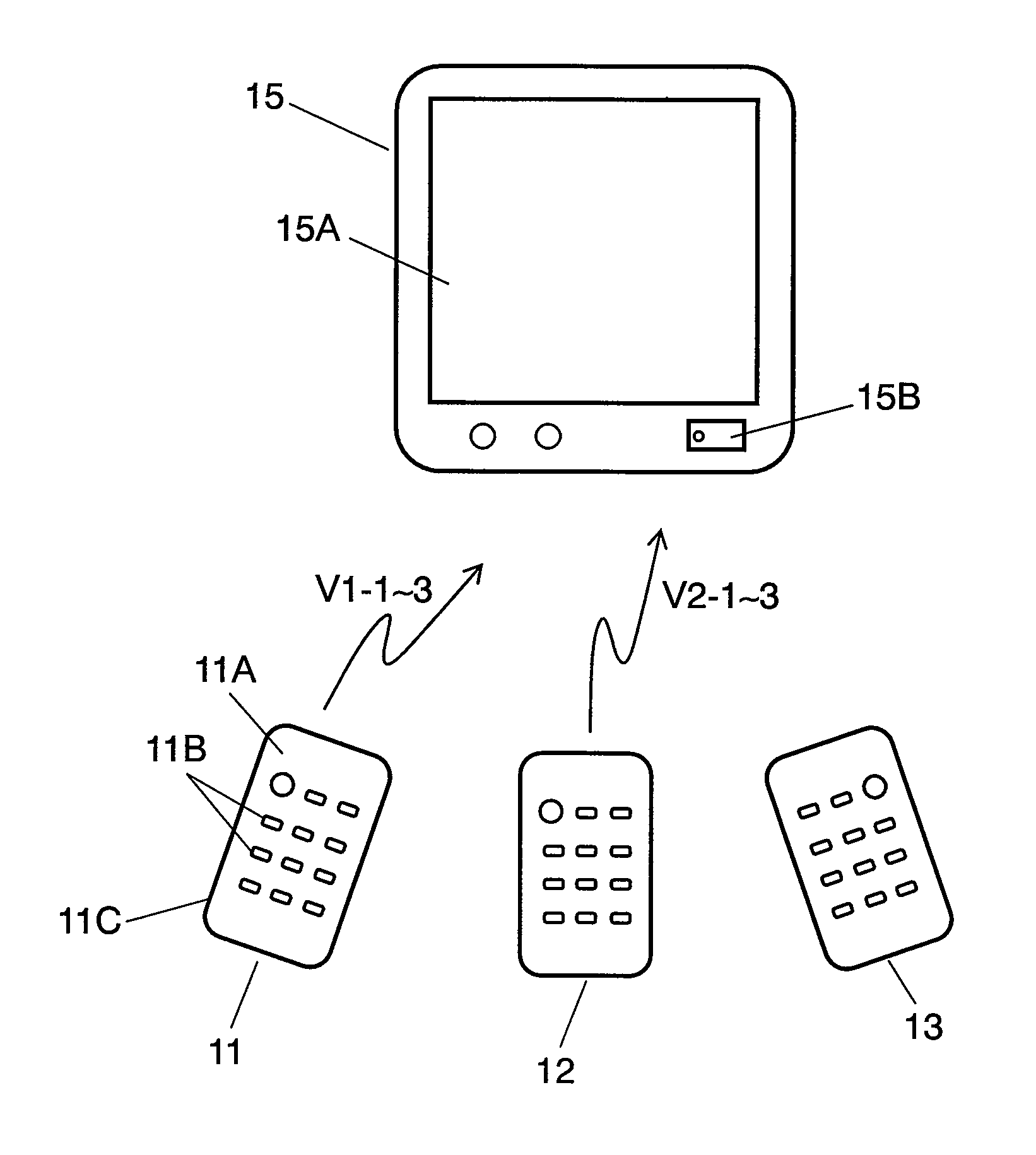
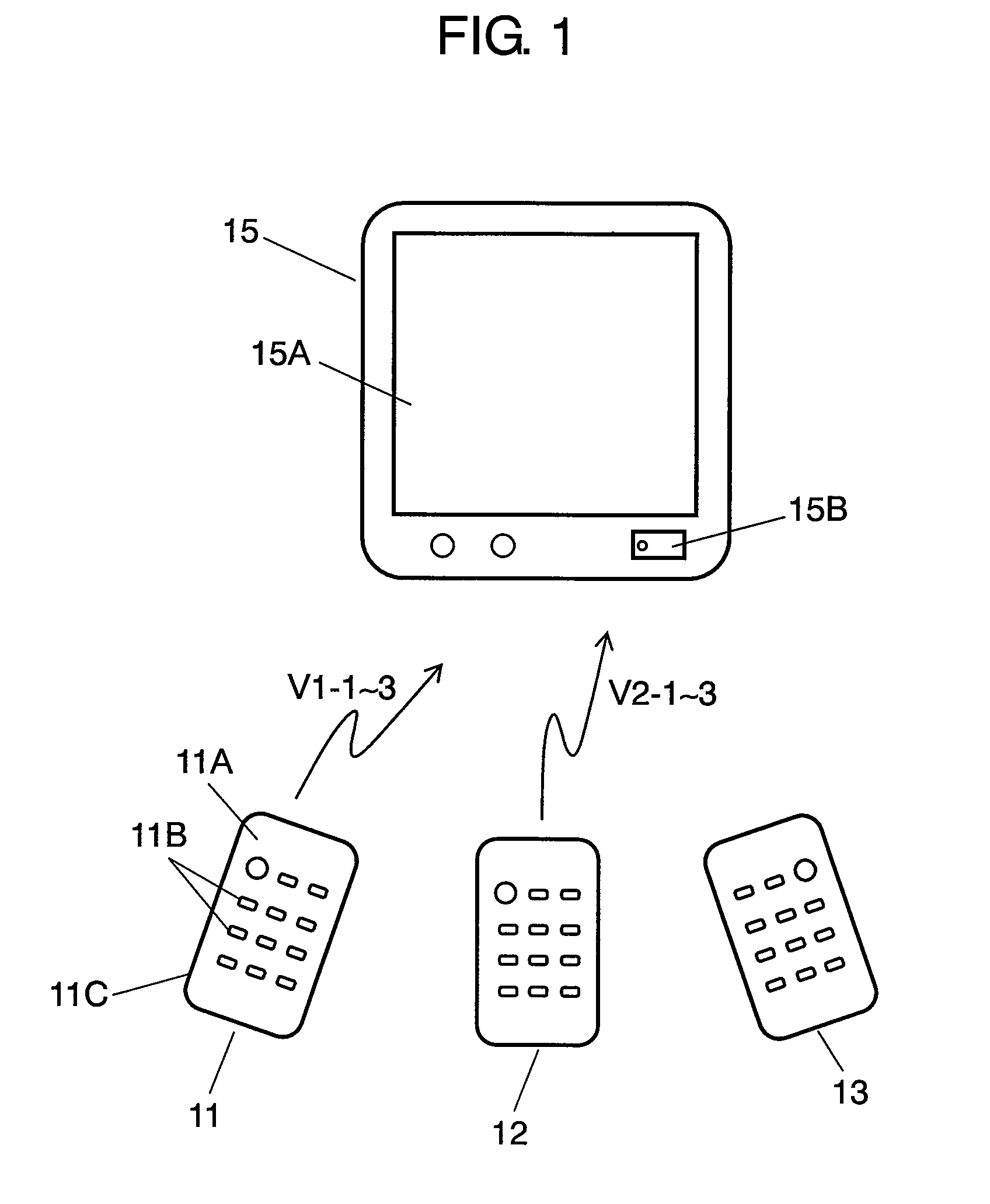
[0023]FIG. 1 is an overall view showing a transmitting-receiving system in accordance with an embodiment of the present invention. In FIG. 1, remote control transmitter 11 includes substantially box-shaped case 11A made of an insulating resin; a plurality of operation keys 11B protruding on the surface of case 11A; switch contacts (not shown) for carrying out electrical connection and disconnection by the operation of case operation keys 11B; and controlling means 11C such as a microcomputer and a light emitting diode for transmitting a remote control signal corresponding to the operation. Receiver 15 includes, in the front surface thereof, display section 15A such as a liquid crystal display device and receiving section 15B such as a microcomputer. A transmitting-receiving system is configured by receiver 15, remote control transmitter 11, and a plurality of remote control transmitters 12 and 13 formed in the same manner as in remote control transmitter 11.

[0024]In the above-mentio...


PUM


Abstract

A remote control transmitting and receiving system for operating electric equipment with little operational misjudgment or malfunction. By setting a plurality of transmission codes of remote control signals of a plurality of remote control transmitters to different periods and by providing transmission order data in these transmission codes, even if transmission is carried out from a plurality of remote control transmitters completely simultaneously or with a slight time difference, it is possible to judge the transmission operation order accurately.

Description

BACKGROUND OF THE INVENTION[0001]1. Field of the Invention[0002]The present invention relates to a remote control transmitter used mainly for operating various electronic equipment and a transmitting-receiving system using the remote control transmitter.[0003]2. Background Art[0004]Recently, remote controlling of various equipment such as video, audio and air conditioning equipment has been widely carried out by using a remote control transmitter. In particular, in a game machine, or the like, a plurality of persons often operate one equipment by using their respective remote control transmitters. Therefore, remote control transmitters with little operational misjudgment or malfunction have been demanded.[0005]Such a conventional remote control transmitter and a transmitting-receiving system using the same are described with reference to FIGS. 6 to 9. FIG. 6 is an overall view showing a conventional transmitting-receiving system. Remote control transmitter 1 shown in FIG. 6 has the ...

Claims


Application Information

Patent Timeline
Patent Type & Authority Patents(United States)
IPC IPC(8): G05B11/01H04L17/02H04J3/06G09B3/00G06F19/00G08B13/14G08B1/08
CPCG08C23/04
Inventor HANAHARA, TETSUROMATSUI, NORIAKI
Owner PANASONIC CORP
Why Eureka
Try Eureka