Remote control transmitter and transmitting-receiving system

Active Publication Date: 2007-09-06
PANASONIC CORP
View PDF6 Cites 1 Cited by
  • Summary
  • Abstract
  • Description
  • Claims
  • Application Information

AI Technical Summary

Benefits of technology

[0012]The present invention provides a remote control transmitter including transmission order data in a plurality of transmission codes of a remote control signal. Code transmission order data showing an ordinal position of each code are provided in a plurality of transmission codes arranged in a predetermined period. Thus, when a transmitting-receiving system is configured by

Problems solved by technology

As described in the above, a remote control transmitter and a transmitting-receiving system according to a conventional technology tend to cause

Method used


Image

  • Remote control transmitter and transmitting-receiving system
  • Remote control transmitter and transmitting-receiving system
  • Remote control transmitter and transmitting-receiving system

Examples


embodiment

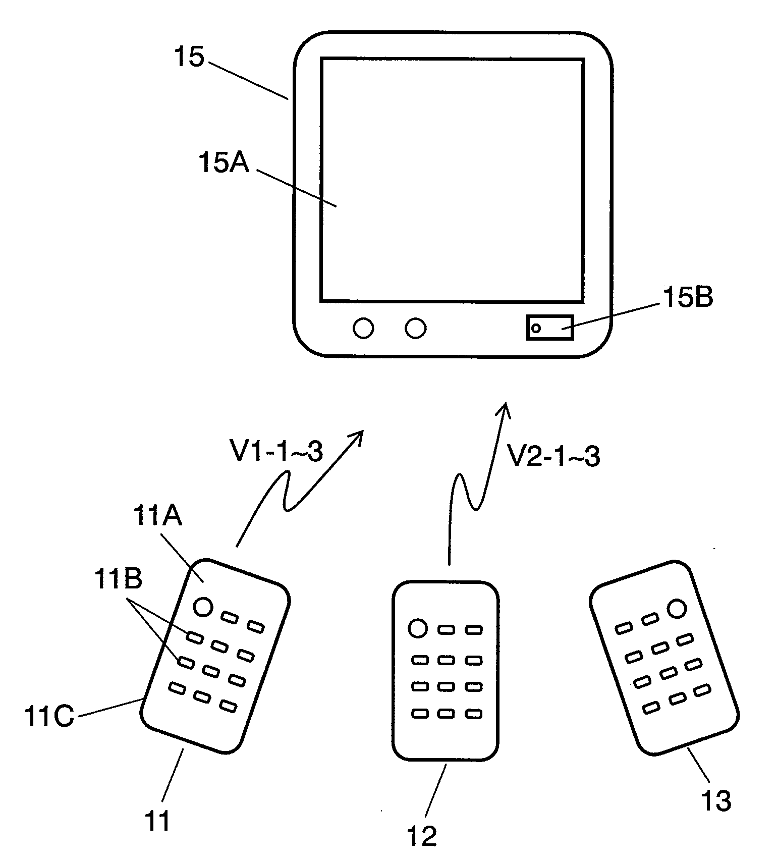
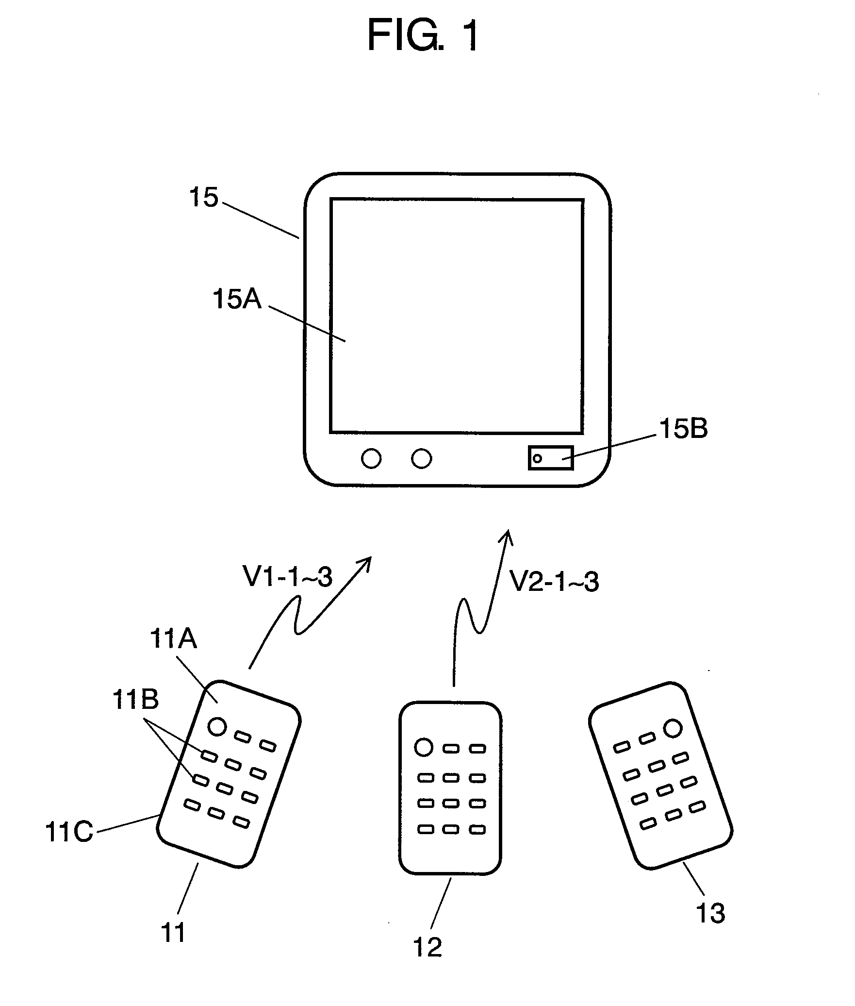
[0023]FIG. 1 is an overall view showing a transmitting-receiving system in accordance with an embodiment of the present invention. In FIG. 1, remote control transmitter 11 includes substantially box-shaped case 11A made of an insulating resin; a plurality of operation keys 11B protruding on the surface of case 11A; switch contacts (not shown) for carrying out electrical connection and disconnection by the operation of case operation keys 11B; and controlling means 11C such as a microcomputer and a light emitting diode for transmitting a remote control signal corresponding to the operation. Receiver 15 includes, in the front surface thereof, display section 15A such as a liquid crystal display device and receiving section 15B such as a microcomputer. A transmitting-receiving system is configured by receiver 15, remote control transmitter 11, and a plurality of remote control transmitters 12 and 13 formed in the same manner as in remote control transmitter 11.

[0024]In the above-mentio...


PUM


Abstract

A remote control transmitting and receiving system for operating electric equipment with little operational misjudgment or malfunction. By setting a plurality of transmission codes of remote control signals of a plurality of remote control transmitters to different periods and by providing transmission order data in these transmission codes, even if transmission is carried out from a plurality of remote control transmitters completely simultaneously or with a slight time difference, it is possible to judge the transmission operation order accurately.

Description

BACKGROUND OF THE INVENTION[0001]1. Field of the Invention[0002]The present invention relates to a remote control transmitter used mainly for operating various electronic equipment and a transmitting-receiving system using the remote control transmitter.[0003]2. Background Art[0004]Recently, remote controlling of various equipment such as video, audio and air conditioning equipment has been widely carried out by using a remote control transmitter. In particular, in a game machine, or the like, a plurality of persons often operate one equipment by using their respective remote control transmitters. Therefore, remote control transmitters with little operational misjudgment or malfunction have been demanded.[0005]Such a conventional remote control transmitter and a transmitting-receiving system using the same are described with reference to FIGS. 6 to 9. FIG. 6 is an overall view showing a conventional transmitting-receiving system. Remote control transmitter 1 shown in FIG. 6 has the ...

Claims


Application Information

Patent Timeline
IPC IPC(8): G08C19/00
CPCG08C23/04
Inventor HANAHARA, TETSUROMATSUI, NORIAKI
Owner PANASONIC CORP
Why Eureka
Try Eureka