
AM to PM correction system for polar modulator

a correction system and polar modulator technology, applied in the field of power amplifier control, can solve the problems of reducing the efficiency of the system that operates the power amplifier

Active Publication Date: 2011-08-02
HUAWEI TECH CO LTD
View PDF129 Cites 5 Cited by
  • Summary
  • Abstract
  • Description
  • Claims
  • Application Information

AI Technical Summary

Benefits of technology

[0012]In another embodiment, the present invention corrects for both AM to PM conversion and AM to AM conversion using similar methodologies. However, the AM to

Problems solved by technology

Such a system lacks the efficiency of one that operates the power amplifier in saturation.
Quadrature modulators are undesirable from a design standpoint in that they draw large amounts of current, and hence, drain batteries comparatively fast.
Analog components cause design problems for polar modulators in that the phase and amplitude signals must be aligned so that they arrive at the power amplifier at the desired time.
Because of path variations with variable time delay analog components, this time aligning is difficult to achieve.
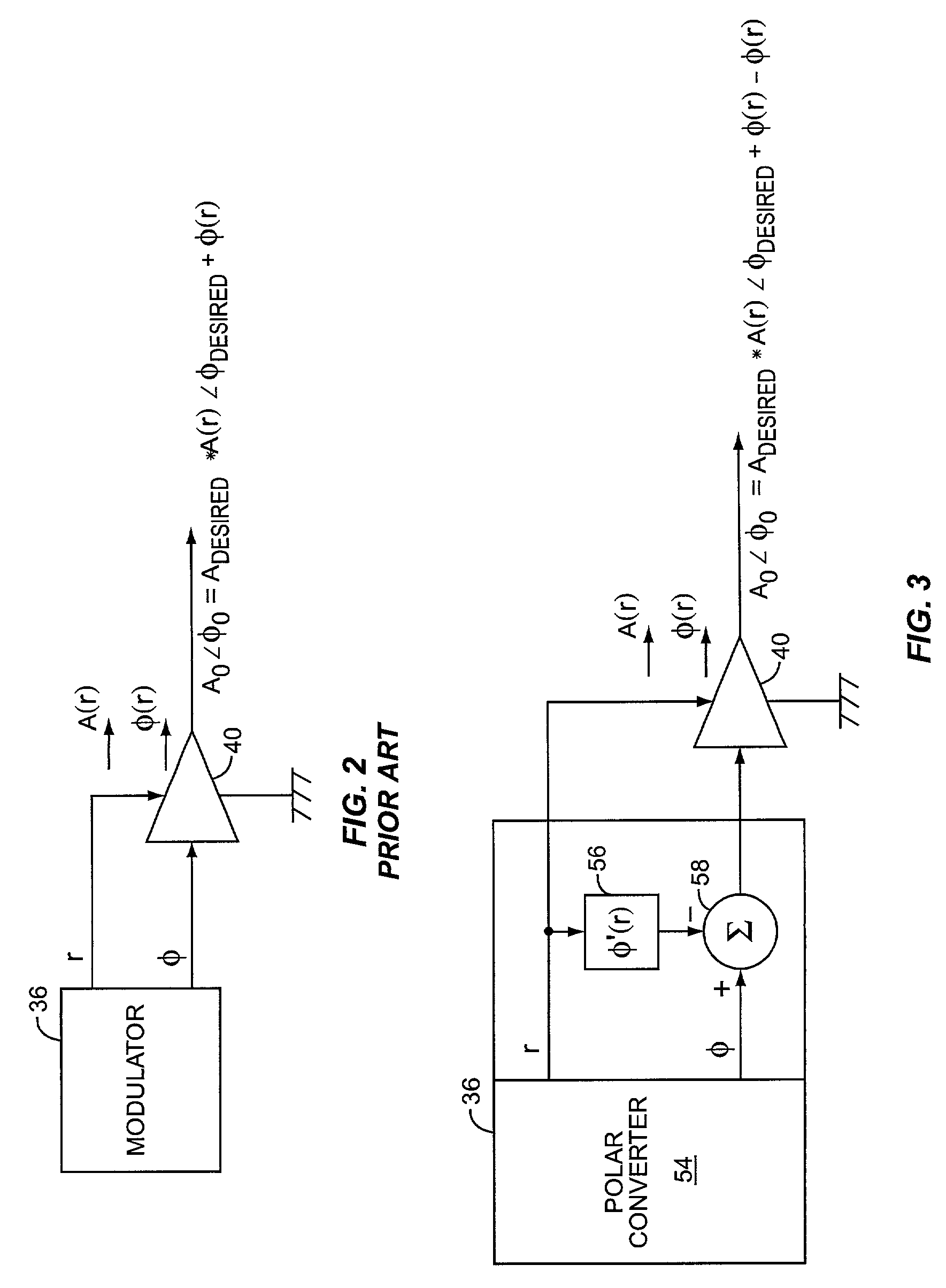
Unfortunately, further complicating matters, the amplitude signal that controls the power amplifier will cause unwanted phase components to be created in the output of the power amplifier due to the non-linearities of the power amplifier.
This is sometimes called AM to PM conversion, and it degrades the spectral purity of the system and the Error Vector Magnitude.

Method used


Image

  • AM to PM correction system for polar modulator
  • AM to PM correction system for polar modulator
  • AM to PM correction system for polar modulator

Examples


Embodiment Construction

[0023]The embodiments set forth below represent the necessary information to enable those skilled in the art to practice the invention and illustrate the best mode of practicing the invention. Upon reading the following description in light of the accompanying drawing figures, those skilled in the art will understand the concepts of the invention and will recognize applications of these concepts not particularly addressed herein. It should be understood that these concepts and applications fall within the scope of the disclosure and the accompanying claims.

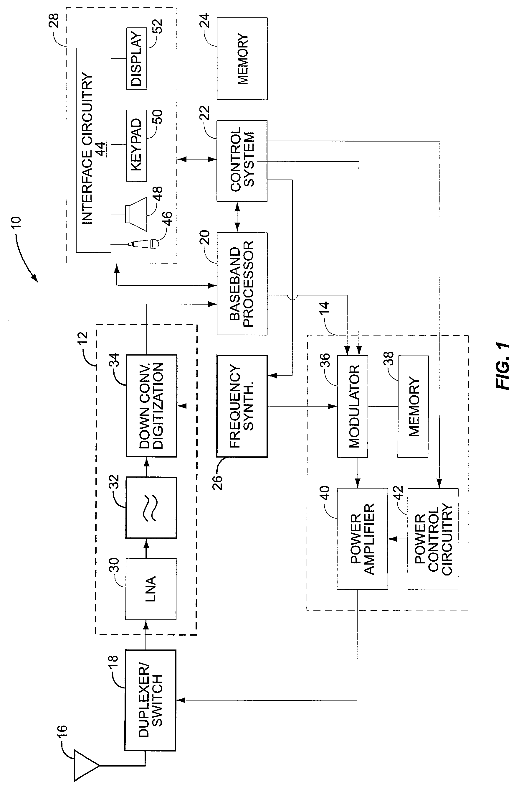
[0024]While the present invention is particularly well-suited for use in a mobile terminal, and particularly a mobile terminal that is operating in an Enhanced Data for GSM Evolution (EDGE) scheme in a GSM system, it should be appreciated that the present invention may be used in other transmitters, either wireless or wirebased, as needed or desired.

[0025]The present invention is preferably incorporated in a mobile terminal 10, su...


PUM


Abstract

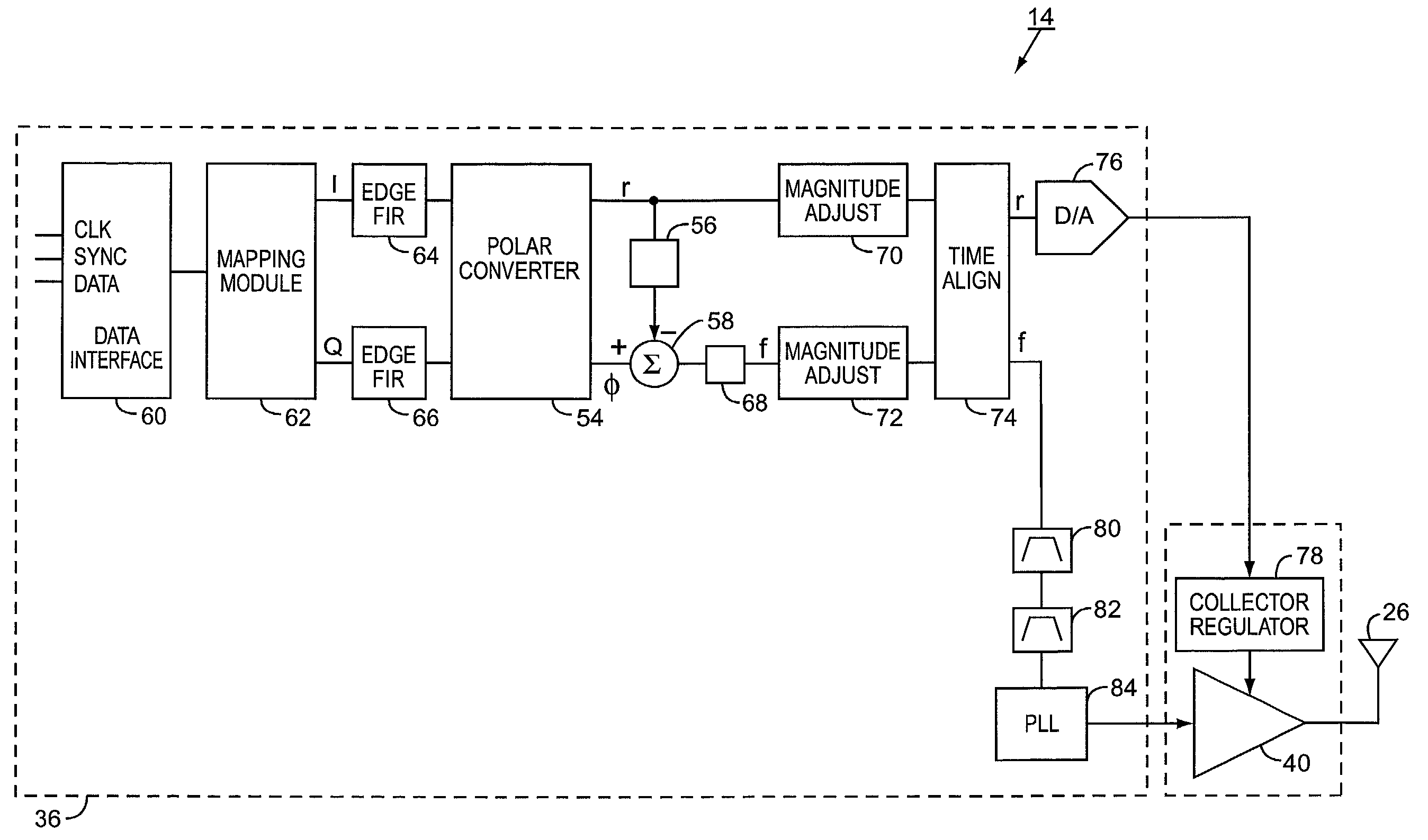
A transmitter includes a polar modulator that creates phase and amplitude signals which in turn drive a power amplifier. To compensate for AM to PM conversion of the amplitude signal into the amplified signal, a compensation signal is generated from the amplitude signal and combined with the phase signal such that when amplified, the compensation signal cancels the AM to PM conversion. The compensation signal may have an offset term, a linear term, a quadratic term, and a cubic term. A second embodiment comprises a technique by which AM to AM conversion may concurrently be addressed using a second compensation signal.

Description

RELATED APPLICATIONS[0001]The present application is related to concurrently filed, commonly assigned, commonly invented U.S. patent application Ser. No. 10 / 147,579, entitled “AM TO AM CORRECTION SYSTEM FOR POLAR MODULATOR.”FIELD OF THE INVENTION[0002]The present invention relates to controlling a power amplifier, and more particularly to controlling the power amplifier in a manner to correct the output Error Vector Magnitude (EVM) and spectrum of the power amplifier.BACKGROUND OF THE INVENTION[0003]Transmitters form one half of most communication circuits. As such, they assume a position of prominence in design concerns. With the proliferation of mobile terminals, transmitter design has progressed in leaps and bounds as designers try to minimize components and reduce size, battery consumption, and the like. Likewise, modulation schemes are continuously updated to reflect new approaches to maximize information transfers in limited bandwidths. Changes in standards or standards based ...

Claims


Application Information

Patent Timeline
IPC IPC(8): H04L25/49H04B1/10H04B15/00H04L27/36
CPCH04L27/361
Inventor HIETALA, ALEXANDER WAYNE
Owner HUAWEI TECH CO LTD
Learn More