
UI display apparatus and method for displaying, on a screen, an icon representing a device connected to a network

a network icon and display method technology, applied in the field of ui display apparatus and ui display method, can solve the problems of poor usability, user inconvenience, inability to perform additional input operations, etc., and achieve the effect of easy search and identification

Inactive Publication Date: 2011-08-02
PANASONIC CORP
View PDF26 Cites 8 Cited by
  • Summary
  • Abstract
  • Description
  • Claims
  • Application Information

AI Technical Summary

Benefits of technology

[0009]The present invention aims at solving the above-described conventional problems, and its object is to provide a UI display apparatus that enables a user to easily select desired device information displayed on the screen in a convenient manner, even in a device with limited operability such as an AV device that uses a remote control and in a device with a small display area such as a mobile phone.
[0013]Accordingly, with the recording unit in which display judgment information is recorded indicating whether or not information should be displayed on the display unit, it is possible for the UI display apparatus according to the present invention to judge in the judgment unit whether or not to display the device-related information from the device on the other end. This makes it possible even for a UI display apparatus connected to many other communication devices via a network to display desired information without having to perform plural screen operations, by allowing only limited information to be displayed on the screen.
[0014]Furthermore, in the UI display apparatus according to the present invention, the obtainment unit obtains the device-related information through the communication unit, using at least one or a combination of communication protocols, and the UI display apparatus further includes a communication status recording unit that records a communication status for each communication protocol, in the case where the communication unit carries out communication using at least one or a combination of communication protocols, and the display unit performs the display in accordance with the communication status recorded in the communication status recording unit and the device-related information obtained by the obtainment unit. Accordingly, even in the case where plural communication protocols are used, it is possible for the UI display apparatus according to the present invention to perform icon display or text display depending on changes in the communication status by the communication status recording unit recording each communication status. This allows the user to easily grasp the communication status of each communication protocol.
[0016]According to the UI display apparatus of the present invention, it is possible to display only necessary device information in an automatic and selective manner from among devices detected on the network, in accordance with a user's preference. Thus, even in a device, such as an AV device, whose operability is relatively low, it is possible to easily search for and identify devices connected to the network in accordance with a user's preference.

Problems solved by technology

However, with the method of the above-mentioned Patent Document 1, when displaying devices connected to the network within a communicable range, there are cases where communication devices on the network cannot be displayed on the single screen all at once and thus they need to be displayed on plural screens due to the fact that the resolution of an AV device is low and other reasons.
When other devices on the network are displayed on plural screens, the user is required to perform plural input operations to search for devices and to identify devices, resulting in the problem of poor usability.
Furthermore, in a device with a narrow display area, such as a mobile phone, there are cases where all communication devices connected to the network cannot be displayed on a single screen, which causes a problem that the user is inconveniently required to perform additional input operations.
Moreover, it is not realistic that the user selects a device to be displayed or a device not to be displayed on the screen, using a remote control with low operability as described above, from among all the devices connected to the network.

Method used


Image

  • UI display apparatus and method for displaying, on a screen, an icon representing a device connected to a network
  • UI display apparatus and method for displaying, on a screen, an icon representing a device connected to a network
  • UI display apparatus and method for displaying, on a screen, an icon representing a device connected to a network

Examples


first embodiment

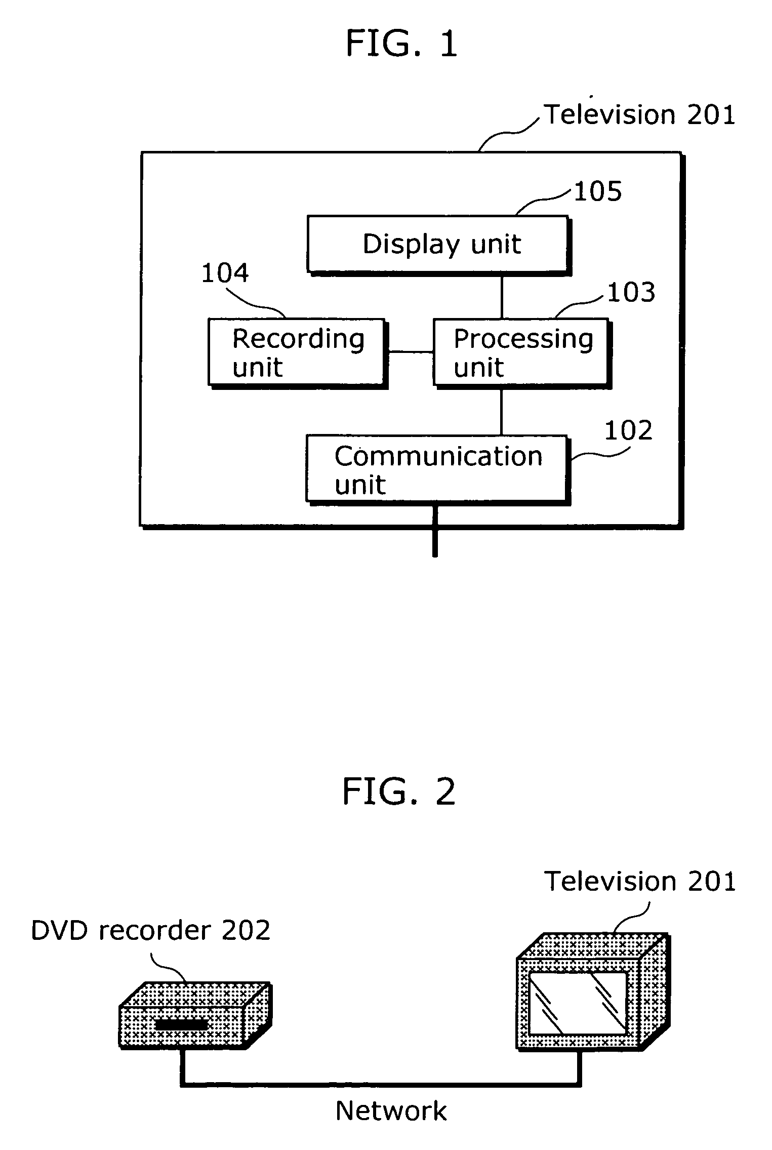
[0051]FIG. 1 is a functional block diagram showing a television 201, which is the UI display apparatus of the first embodiment. This television 201 displays, on the screen, devices that are connected via a network as icons, and includes a communication unit 102, a processing unit 103, a recording unit 104, and a display unit 105.

[0052]The communication unit 102 communicates with a DVD recorder, which is a communication device connected via the network. The communication unit 102 receives data sent from the DVD recorder via the network, and sends the data to the processing unit 103. Furthermore, the communication unit 102 sends data which is requested by the processing unit 103 to send to the DVD recorder on the network.

[0053]The processing unit 103 instructs the display unit 105 to perform UI rendering based on information stored in the recording unit 104. Furthermore, it performs processing according to data notified from the communication unit 102.

[0054]Stored in the recording uni...

second embodiment

[0077]Next, a UI display apparatus according to the second embodiment is described. Note that the second embodiment is characterized in that the television 201 requests the DVD recorder 202 for device information, so that the television 201 which has received a network-join notice 702 authenticates that the DVD recorder 202, which is the device on the other end, is an authorized device.

[0078]FIG. 9 shows a communication sequence from when the UI display apparatus of the second embodiment detects a device which has newly joined the network until when it notifies the user of such fact. Note that in FIG. 9 and FIG. 10, the same constituent elements and procedures as those shown in FIG. 5 and FIG. 6 described in the above-described first embodiment are assigned the same reference numbers, and their detailed descriptions are not given.

[0079]In the case of judging, after receiving the network-join notice 702 in S502, that it is necessary to display, on the display unit 105, the device whi...

third embodiment

[0086]Next, a UI display apparatus according to the third embodiment is described. Note that the third embodiment is characterized in that the television 201 can check an action and content information held by the DVD recorder 202 being the device which has joined the network, by the television 201 on the UI display apparatus side requesting the DVD recorder 202 for device service information.

[0087]FIG. 12 shows a communication sequence from when the television 201 being the UI display apparatus of the third embodiment detects a device which has newly joined the network until when it notifies the user of such fact. Note that in FIG. 12 and FIG. 13, the same constituent elements and procedures as those shown in the above-described embodiments are assigned the same reference numbers, and their detailed descriptions are not given. Also note that the processes until S904 in FIG. 12 and the processes until S1004 in FIG. 13 are the same as those of the above-described second embodiment, a...


PUM


Abstract

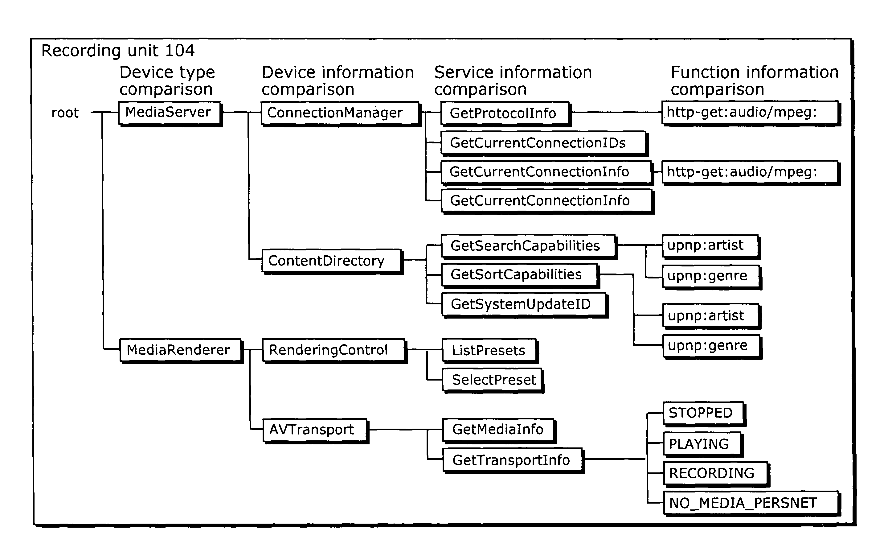
An UI display apparatus capable of searching for and identifying a communication device connected to a network, in accordance with a user's preference. A television being the UI display apparatus includes a communication unit communicating with a DVD recorder, which is a communication device connected via the network, receiving data sent from the DVD recorder via the network, and sending the received data to the processing unit, and a processing unit instructing the display unit to perform UI rendering based on information stored in a recording unit, the recording unit storing the type name of a device the television wishes to display on the display unit among the devices on the network, the type name of a service provided by the device, a function name, etc. The television also includes a display unit displaying a UI such as an icon according to an instruction from the processing unit.

Description

FIELD OF INVENTION[0001]The present invention relates to a UI display apparatus and a UI display method for displaying a device connected to a network on a screen of a device connected to the network, and particularly to a UI display apparatus that displays a device connected to the network on a screen of an AV device.DESCRIPTION OF THE RELATED ART[0002]As a method for displaying devices connected to a network, there has been conventionally proposed an information processing apparatus that displays, to a user, the join state of information devices on the network in an easy-to-understand manner, when displaying devices joining a wired and / or wireless network, by changing the display details in a stepwise manner in accordance with network communication status, join / withdrawal time, join / withdrawal rate, the number of joins / withdrawals of the information devices (for example, refer to Patent Document 1, Japanese Laid-Open Patent Application No. 2003-134127).[0003]Also, as a possible me...

Claims


Application Information

Patent Timeline
IPC IPC(8): G06F15/173G06F13/00G06F3/00G06F3/048G06F3/0481
CPCH04L12/2809H04L41/22H04N1/00291H04N1/00347H04L67/306H04N1/00503H04L67/36H04N1/0035H04L12/281H04L2012/2849H04N2201/0036H04N2201/0039H04L67/16H04L67/51H04L67/75G06F13/00G06F3/0481
Inventor KATO, NAONORITAKECHI, HIDEAKINAKATSUKA, MONTAYAMAMOTO, MUTSUKO
Owner PANASONIC CORP
Learn More