Tension reducer for cable wrap security device

a technology of tension reducer and security device, which is applied in the direction of alarm locks, hose connections, lock applications, etc., can solve the problems of not being able to read information, not being able to handle the article, and being faced with the problem of how to protect expensive items, etc., to achieve easy retrofit, increase the amount of friction, and increase the effect of friction

Inactive Publication Date: 2011-08-09
CHECKPOINT SYST INC
View PDF13 Cites 17 Cited by
  • Summary
  • Abstract
  • Description
  • Claims
  • Application Information

AI Technical Summary

Benefits of technology

[0013]Another feature is to provide such a security device with a tension reducer which operatively engages one or more of the cable loops as they extend outwardly from the housing and provides an abrupt change in direction of the cable loop and increased friction on the cable loops whereby a large force suddenly exerted on the cable loops is reduced considerably before the force is transmitted onto the internal ratchet mechanism within the housing thereby protecting the ratchet mechanism from damage and possible failure.
[0014]Another feature of the present invention is to provide the tension reducer as an adapter which is easily retrofitted onto existing cable wrap security devices which is in the form of a collar that is snap-fitted onto the bottom of the security device, which adapter requires the cable loops upon exiting the ratchet housing to pass beneath the collar before extending along the protected object thereby providing the abrupt change in the direction of the cable loops, or which directs the loops between the collar and bottom of the housing along projections formed on the collar to increase the amount of friction exerted on the loops immediately after exiting the spool housing to reduce the amount of force exerted on the ratchet mechanism.
[0015]A further feature of the present invention is to provide the cable tension reducer as a simple ring-like member through which one or two pairs of the cable loops pass upon exiting the ratchet housing before extending along the protected object thereby providing for the desired change in direction of the cable loops to appreciably reduce the amount of force transmitted from the cable loops onto the internal ratchet mechanism of the security device.

Problems solved by technology

Retail stores have a difficult time protecting objects such as boxes containing various expensive merchandise, books and other similarly structured packages, or protecting such containers from being opened and the contents thereof being removed without authorization from store personnel or damaged while on display.
The store is faced with the problem of how to protect these expensive articles from theft while displaying them for sale.
The consumer can view the article through the glass but is not able to handle the article or read any of the information about the article that may be printed on the box unless a store clerk removes the article from the case.
However, in large retail stores, the problem then arises of getting the selected merchandise to the customer after the customer wishes to purchase the same without subjecting the merchandise to theft.
However this makes the boxes susceptible to theft and requires additional sales personnel.
The consumer does not get to inspect the article before purchasing and if they are not satisfied they must undergo the hassle of returning the article for a refund.
Boxes and similar objects are also subjected to unauthorized openings while being shipped via a courier.
Shipped packages can be secured within a security container with a locking mechanism but these containers are expensive to purchase and add size and weight to the package making it more expensive to ship.
Also, would-be thieves can gain unauthorized access to the contents of these containers by “picking” the locking mechanisms or possibly guessing the combination to a combination lock.
However, it has been discovered that if an abrupt force is exerted on the cable loops, such as by lifting a heavy package by the security device and simulating a sudden dropping of the package while continuing to grasp the security device, it would exert a large abrupt force on the cable loops that is transmitted directly to the internal ratchet mechanism possibly causing breakage of the ratchet mechanism enabling the cable to unwind freely from the cable storage spool mounted within the security device exposing the protected object to unauthorized entry or removal of the security device cable loops therefrom due to the unwinding of the cable loops from the internal spool of the security device.

Method used


Image

  • Tension reducer for cable wrap security device
  • Tension reducer for cable wrap security device
  • Tension reducer for cable wrap security device

Examples


first embodiment

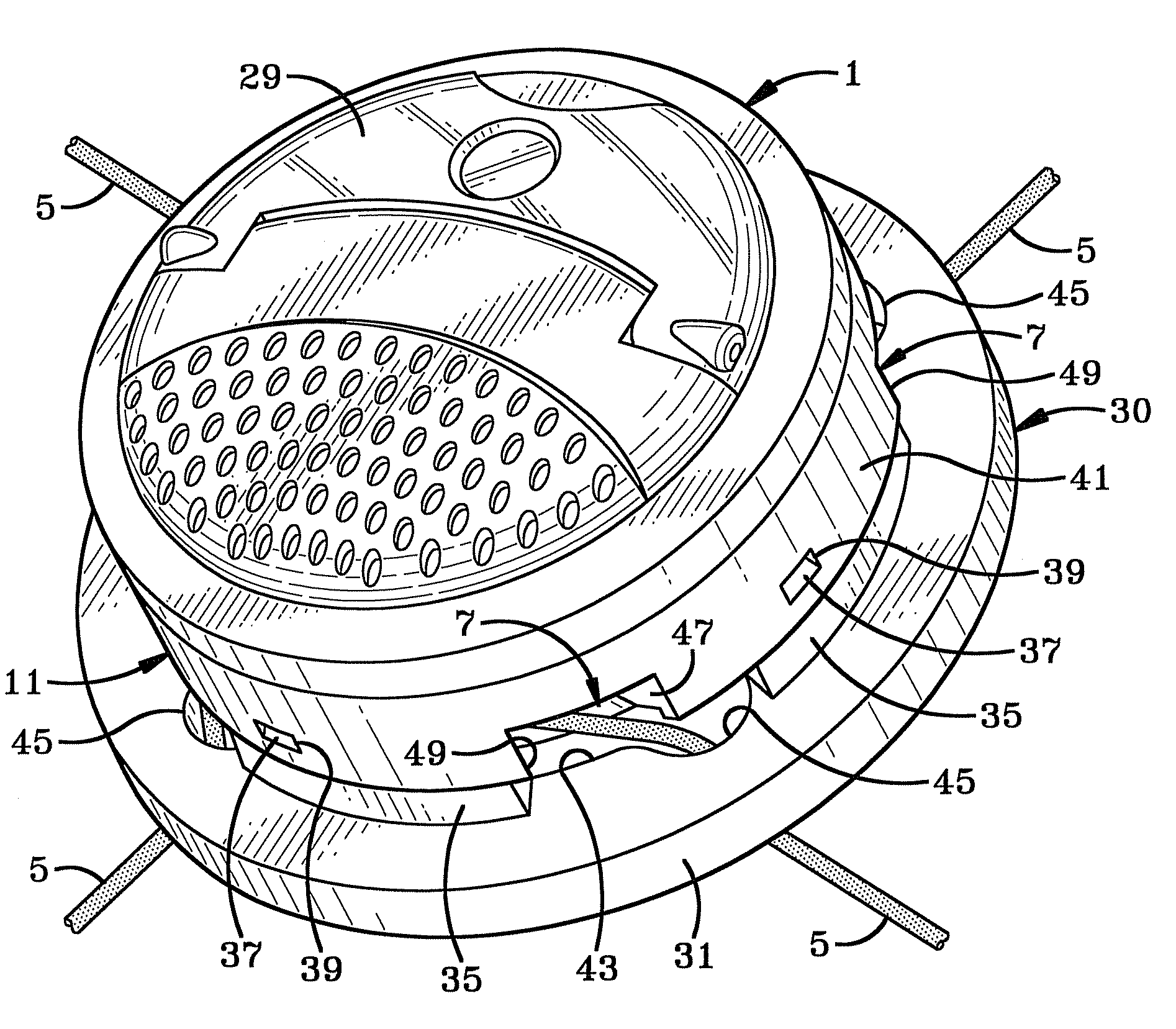
[0045]In accordance with the present invention, in order to reduce the amount of force F from being exerted directly onto the ratchet mechanism, a tension reducer indicated generally at 30, and shown in FIGS. 8-12, is mounted on security device 1. Tension reducer 30 includes an annular collar 31 having a central opening 33 and is provided with a plurality of upstanding arcuate-shaped projections 35, each of which is formed with one or more one-way snap-fit tabs 37. Tabs 37 are adapted to be snap-fitted into aligned openings 39 formed in side wall 41 (FIG. 9) of security housing 11 to securely attach tension reducer 30 onto the bottom of security device 1. The inner peripheral wall 43 of collar 31 which forms central opening 33, preferably is formed with an outwardly extending recess 45 between each of the arcuate projections 35, which recesses are adapted to receive one of the cable loops 5 therein as shown particularly in FIGS. 9-12. Recesses 45 preferably are positioned with respe...

second embodiment

[0046]the tension reducer which will achieve a similar abrupt change of direction of cable loops 5 is shown particularly in FIGS. 13 and 14. This embodiment includes the use of an annular ring 51 which will be located between adjacent housing openings 7 as shown in FIG. 13. Adjacent pairs of cable loops 5 will pass through a central opening 53 of ring 51 before extending outwardly along the adjacent surface of object 3. With this arrangement, security device 1 lies flatter against the top surface of object 3 as shown by comparing FIGS. 11 with that of FIG. 14, yet still provides the abrupt approximately 90° change in direction of the cable loops after exiting housing openings 7 as shown in FIG. 13. Thus, again, when a large force F is exerted on the cable loops, it is considerably reduced due to the change of direction of the cable loops and resulting frictional force created thereby as they pass through ring 51 before entering in a generally tangential direction about the spool as ...

fourth embodiment

[0048]the cable tension reducer of the present invention is indicated generally at 65 and is shown in FIGS. 18-21. Tension reducer 65 includes a circular snap-on collar 67 which is very similar to collar 31 of tension reducer 30 shown in FIG. 8. Tension reducer collar 67 has four arcuate-shaped projections 69 formed integrally thereon which extend about a central opening 71. A snap-fit tab 73 is formed adjacent one end of each projection 69 and is snap-fitted into aligned openings 39 formed in sidewall 41 (FIG. 19) of cylindrical housing 11 to securely attach collar 67 onto the bottom of security device 1 in a similar manner as is collar 31 attached to housing 11. Projections 69 have a stepped configuration which form an annular ledge 75 on which the bottom edge of housing sidewall 41 seats when tabs 73 extend through openings 39. This provides a space 77 between top surface 79 of collar 67 and bottom surface 59 of housing sidewall 41. Arcuate projections have an arcuate length of a...


PUM


Abstract

A security device includes a housing containing a ratchet mechanism and a rotatable spool for storing a plurality of cable loops which extend outwardly from a plurality of openings formed in the housing and wrapped around the sides of a box-like object. A collar is mounted on the bottom of the housing and has openings adjacent each of the housing opening requiring the cable loops to abruptly change direction after exiting the housing and passing either beneath or above the collar before extending along the secured object. This abrupt change of direction reduces the amount of force which are exerted on the cable loops from being transmitted onto the ratchet mechanism. In alternate embodiments, adjacent cable loops pass through one or a pair of rings which cause a change of direction in the cable loops to reduce the transmission of forces onto the ratchet mechanism.

Description

CROSS REFERENCE TO RELATED APPLICATIONS[0001]This application claims priority from U.S. Provisional Application Ser. No. 60 / 923,368 filed Apr. 13, 2007; the disclosure of which is incorporated herein by reference.BACKGROUND OF THE INVENTION[0002]1. Technical Field[0003]The invention relates to a security device, and more particularly, to a security device which wraps around and secures a box-like structure in a secure locked position. Even more particularly, the invention relates to such a cable security device which includes a device that reduces a force which is applied to the cable loops from being fully transmitted to a spool and ratchet mechanism within the security device to prevent malfunction of the ratchet mechanism.[0004]2. Background Information[0005]Retail stores have a difficult time protecting objects such as boxes containing various expensive merchandise, books and other similarly structured packages, or protecting such containers from being opened and the contents th...

Claims


Application Information

Patent Timeline
Patent Type & Authority Patents(United States)
IPC IPC(8): E05B43/00
CPCE05B45/005E05B73/0017E05B73/0029Y10T24/2138Y10T24/1404Y10T24/39Y10T24/2158
Inventor GOLDSTEIN, MITCHELL S.MOOCK, ANDREW W.FAWCETT, CHRISTOPHER J.
Owner CHECKPOINT SYST INC
Why Eureka
Try Eureka