Reflector and lighting apparatus comprising reflector

a technology of reflectors and lighting apparatuses, which is applied in the direction of lighting and heating apparatuses, fixed installations, semiconductor devices for light sources, etc., can solve the problems of easy warpage or deformation, and no longer be able to achieve desired luminous intensity distribution control, so as to prevent warpage and deformation of itself

Inactive Publication Date: 2011-08-09
TOSHIBA LIGHTING & TECH CORP +1
View PDF41 Cites 14 Cited by
  • Summary
  • Abstract
  • Description
  • Claims
  • Application Information

AI Technical Summary

Benefits of technology

[0009]An object of the present invention is to provide a reflector which can prevent the warpage and deformation of itself caused by heat, thereby enabling a desired luminous intensity distribution control, and illumination apparatus equipped with this reflector.

Problems solved by technology

For this reason, reflectors are easily warped or deformed due to heat, and if the reflection surfaces are deformed, it is no longer possible to perform desired luminous intensity distribution control.
However, this publication makes no mention of means for assuring the desired luminous intensity distribution control by preventing the warpage and deformation of the lens body caused by heat.

Method used


Image

  • Reflector and lighting apparatus comprising reflector
  • Reflector and lighting apparatus comprising reflector
  • Reflector and lighting apparatus comprising reflector

Examples


Embodiment Construction

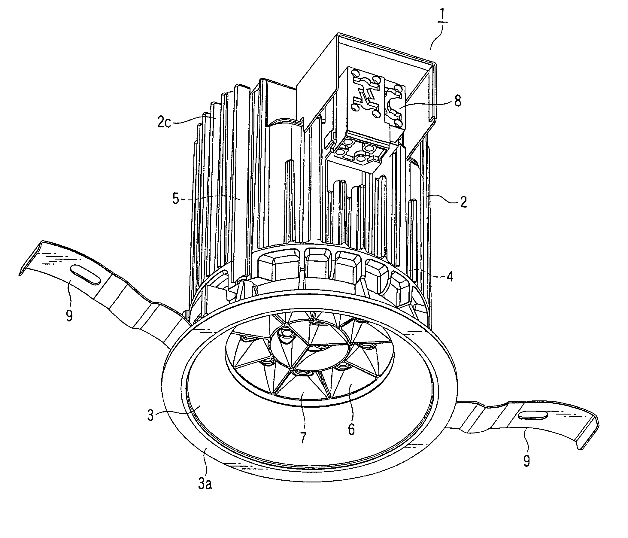
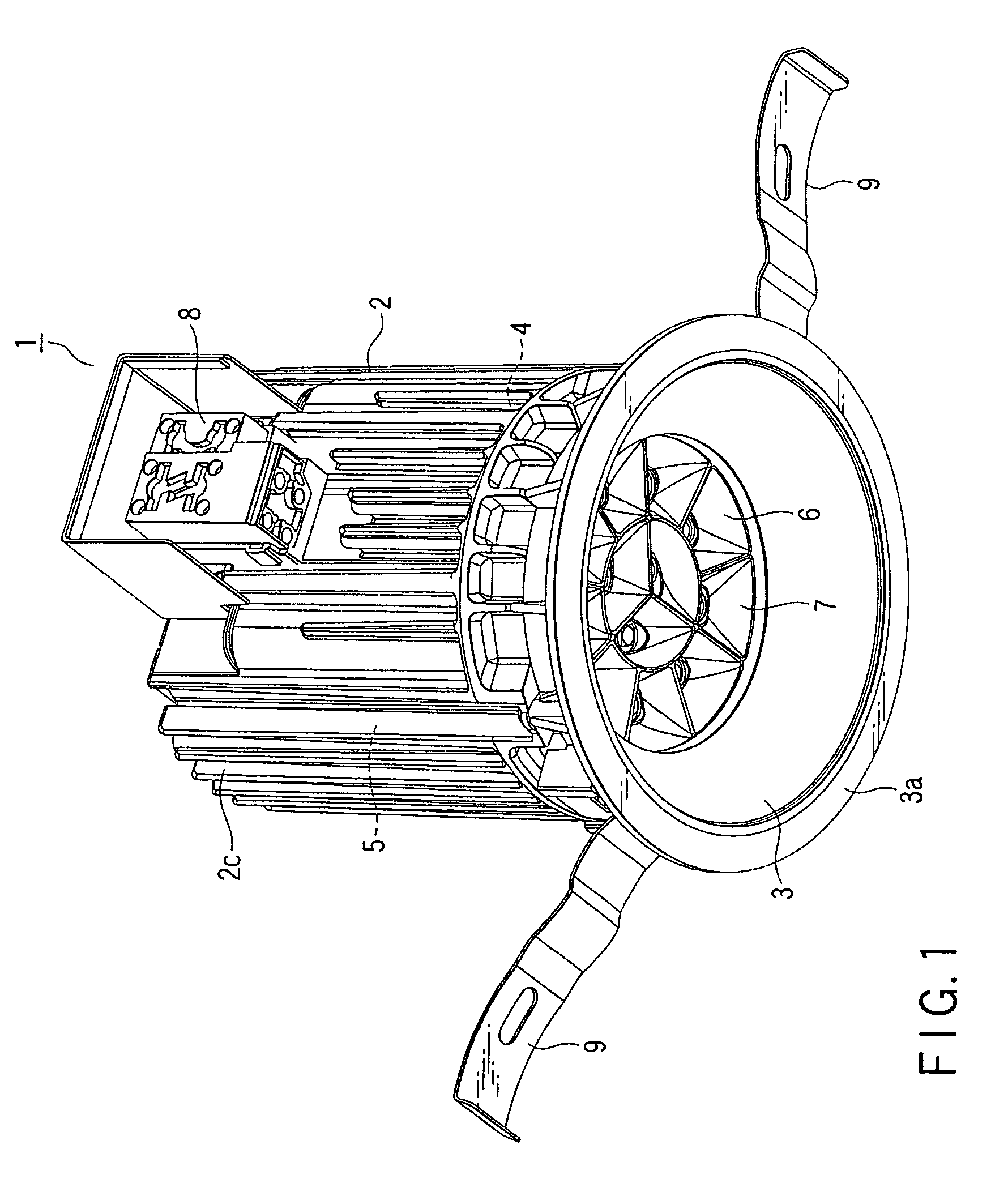
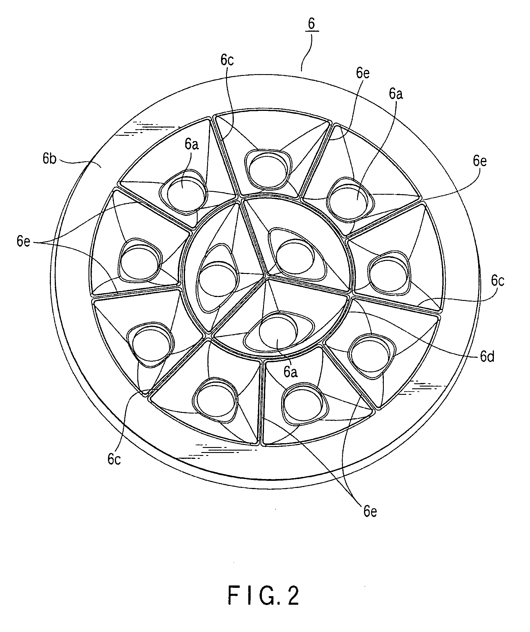
[0023]A reflector and lighting apparatus according to the first embodiment of the present invention will now be described with reference to FIGS. 1 to 7. As an example of the lighting apparatus, the case where the present invention is applied to a down light 1 will be discussed.

[0024]FIG. 1 is a perspective view of the down light 1, FIG. 2 is a perspective view of a reflector 6 built in the down light 1, FIG. 3 is a diagram of the reflector 6 viewed from a front surface side, FIG. 4 is a cross sectional view taken along the line IV-IV in FIG. 3, FIG. 5 is a cross sectional view taken along the line V-V in FIG. 3, FIG. 6 is a diagram of a substrate 4 built in the down light 1 shown in FIG. 1, viewed from a front surface side, FIG. 7 is a partially enlarged cross sectional view of the down light 1 shown in FIG. 1, the main portion thereof being illustrated on larger scale.

[0025]As light-emitting elements serving as the light source of the down light 1, solid-state light-emitting eleme...


PUM


Abstract

A reflector built in a down light includes a plurality of floodlight openings respectively exposing a plurality of light-emitting elements to a front surface side, a plurality of radial partition walls which respectively partition and surround these floodlight openings, and an inner circumferential partition wall. Each of the partition walls has a ridge line, and the reflector includes a plurality of reflection concave surfaces each which open and widen from a respective one of the plurality of floodlight openings towards ridge lines of the plurality of partition walls which respectively surround the plurality of floodlight openings. The plurality of radial partition walls extend from the center of the reflector towards the outer circumference, and the inner circumferential partition wall is located between the center and the outer circumference.

Description

CROSS-REFERENCE TO RELATED APPLICATIONS[0001]This application is based upon and claims the benefit of priority from prior Japanese Patent Applications No. 2008-134855, filed May 22, 2008; and No. 2009-071275, filed Mar. 24, 2009, the entire contents of both of which are incorporated herein by reference.BACKGROUND OF THE INVENTION[0002]1. Field of the Invention[0003]The present invention relates to a reflector suitable for a lighting apparatus which uses a plurality of light-emitting elements such as LEDs, and to a lighting apparatus including the reflector.[0004]2. Description of the Related Art[0005]Recently, lighting apparatus which uses a plurality of light-emitting elements such as LEDs as light sources have been developed. For lighting apparatus of this type, there has been an increasing demand of increasing their outputs, and also a tendency of increasing light-emitting element employed in the apparatus. Further, such lighting apparatus which employs a plurality of light-emitt...

Claims


Application Information

Patent Timeline
Patent Type & Authority Patents(United States)
IPC IPC(8): F21V7/00
CPCF21S8/02F21V7/0083F21V17/12F21V29/763F21V29/75F21V29/004F21Y2101/02F21Y2105/18F21Y2115/10F21V29/70
Inventor MORIYAMA, TAKAYOSHIHIGUCHI, KAZUNARIHASHIMOTO, SUMIOKUMASHIRO, SHINICHI
Owner TOSHIBA LIGHTING & TECH CORP
Why Eureka
Try Eureka