Free vortex air-oil separator

a technology of air-oil separator and free vortex, which is applied in the direction of liquid fuel engine, separation process, liquid degasification, etc., can solve the problems of loss of oil contained in air/oil mixture, unrecoverable oil, and high oil consumption

Active Publication Date: 2011-08-09
GENERAL ELECTRIC CO
View PDF12 Cites 24 Cited by
  • Summary
  • Abstract
  • Description
  • Claims
  • Application Information

AI Technical Summary

Problems solved by technology

Oil consumption arises from the method used to seal the bearing sumps.
This flow ultimately contains oil that is unrecoverable unless adequately separated and delivered back to the sumps.
Oil that is contained in the air / oil mixture is lost when it is unable to centrifuge back into the sump through the vent hole due to rapidly escaping vent air.
These devices are typically limited in their separation strength and thus efficiency.
Air-oil separation is particularly poor in these conventional designs in cases where the axial distances are short in the sump region.
It has been found that without adequate dwell time for vortex motion, oil separation from the air-oil mixture will be poor.
It is more difficult to separate the oil from the air-oil mixture at higher temperatures.

Method used


Image

  • Free vortex air-oil separator
  • Free vortex air-oil separator
  • Free vortex air-oil separator

Examples


Embodiment Construction

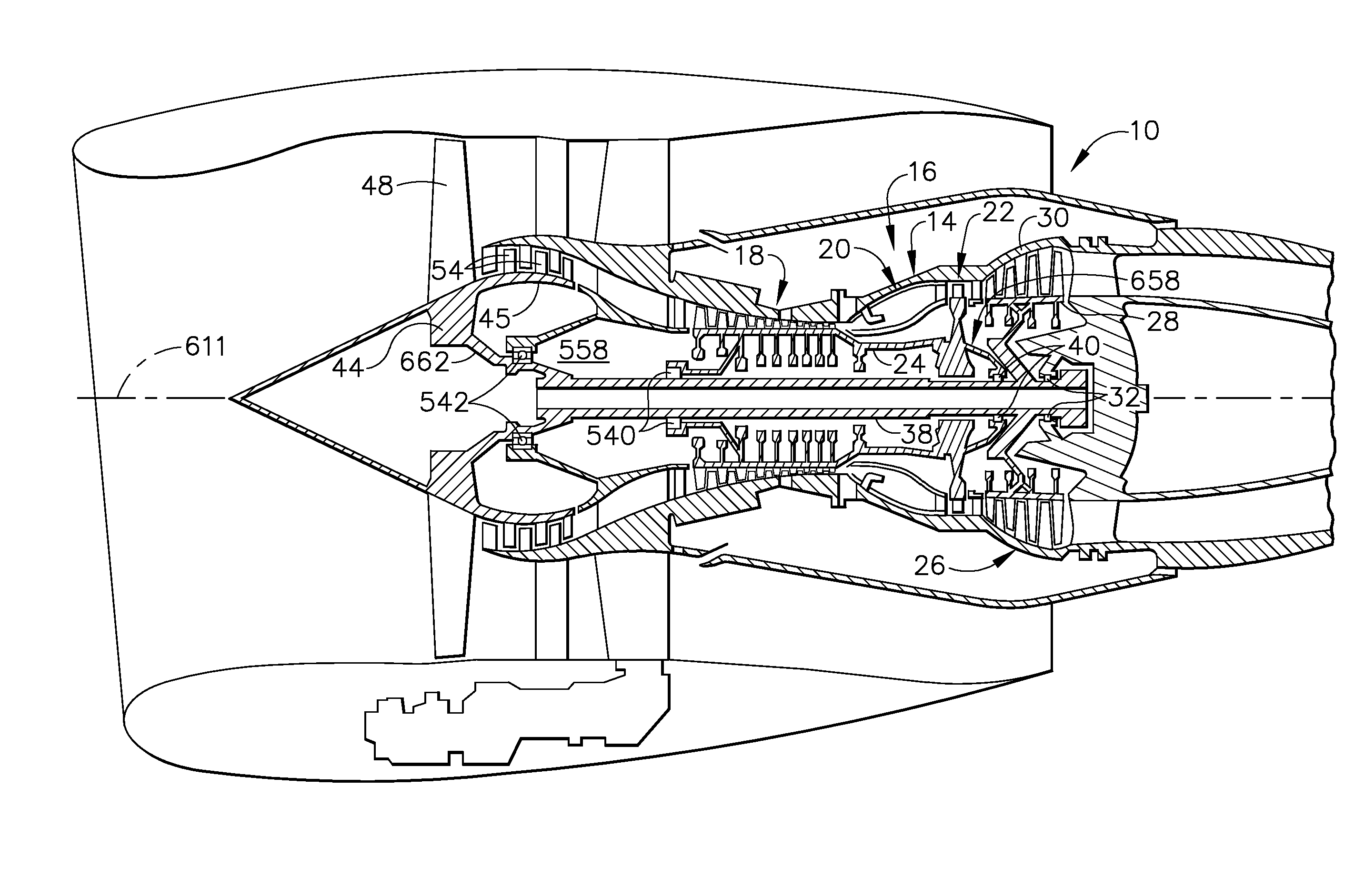
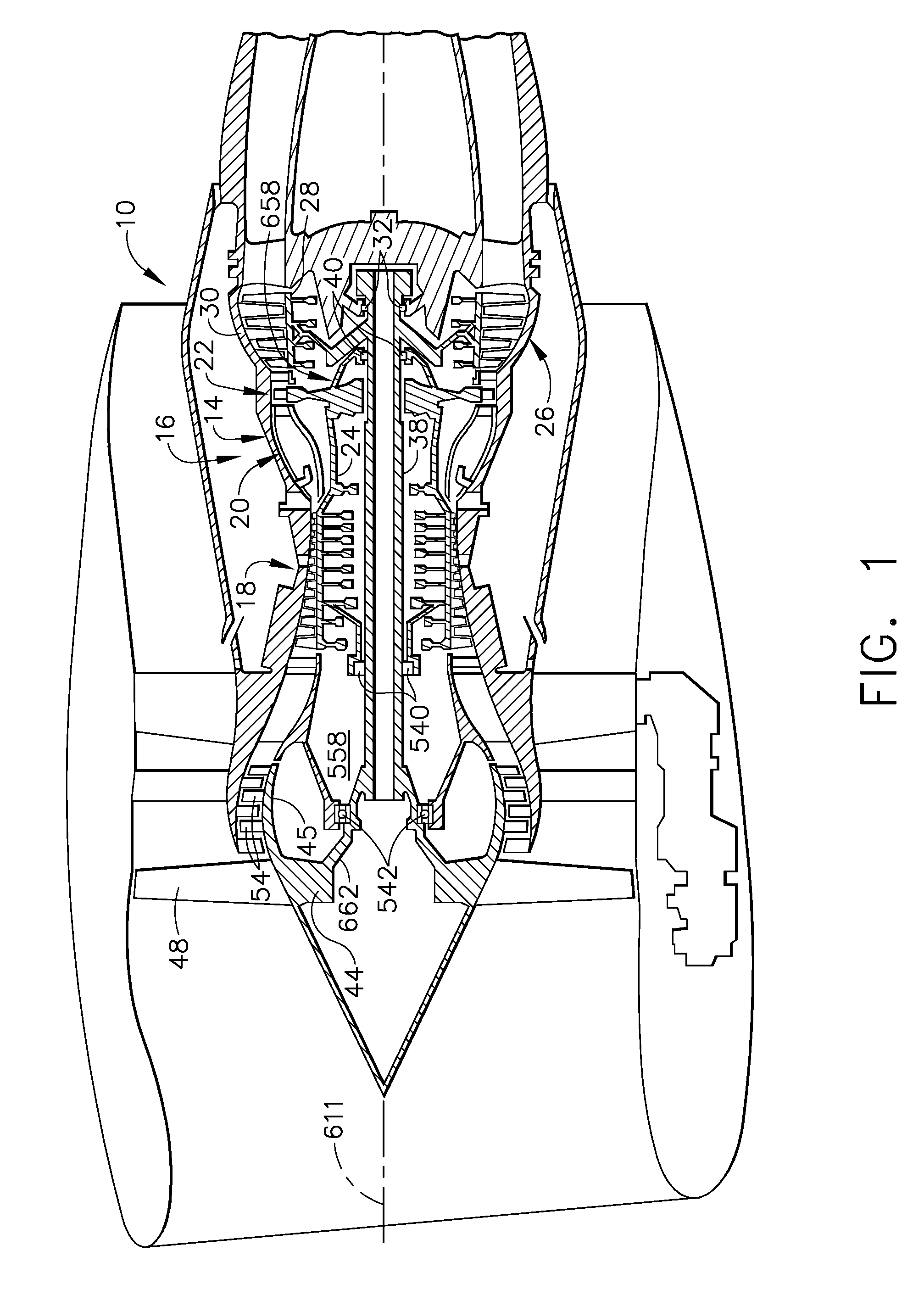
[0014]Referring to the drawings wherein identical reference numerals denote the same elements throughout the various views, FIG. 1 illustrates a gas turbine engine, generally designated 10, incorporating an exemplary embodiment of a free vortex air-oil separator of the present invention. The engine 10 has a longitudinal centerline or axis 611 and an outer stationary annular casing 14 disposed concentrically about and coaxially along the axis 611. The engine 10 includes a gas generator core 16 which is composed of a multi-stage compressor 18, a combustor 20, and a high pressure turbine 22, either single or multiple stage, all arranged coaxially about the longitudinal axis or center line 611 of the engine 10 in a serial, axial flow relationship. An annular outer drive shaft 24 fixedly interconnects the compressor 18 and high pressure turbine 22.

[0015]The core 16 is effective for generating combustion gases. Pressurized air from the compressor 18 is mixed with fuel in the combustor 20 ...


PUM

PropertyMeasurementUnit
radiusaaaaaaaaaa
diameteraaaaaaaaaa
particle sizeaaaaaaaaaa

Abstract

The present invention provides a free vortex air-oil separator that may be used in systems for separating oil from air oil mixtures. The free vortex air-oil separator comprises a free vortex chamber having a first chamber wall, a second chamber wall located axially aft from the first chamber wall and a rim located in a radially outer region from an axis of rotation, a plurality of vent holes in the rim and a cavity formed by the first and second chamber walls, and the rim, wherein a free vortex is created when there is a flow into the cavity through the plurality of vent holes.

Description

CROSS REFERENCE TO RELATED APPLICATIONS[0001]This specification is related to and incorporates herein by reference U.S. application Ser. No. 11 / 946,103, entitled “AIR-OIL SEPARATOR” and U.S. application Ser. No. 11 / 946,111, entitled “VORTEX AIR-OIL SEPARATOR SYSTEM” which were filed concurrently with this application.BACKGROUND OF THE INVENTION[0002]This invention relates generally to gas turbine engines and more particularly to a free vortex air oil separator for recovering oil used to lubricate and cool bearings used in gearboxes and other components of a gas turbine engine.[0003]Gas turbine engines typically include a core having a compressor for compressing air entering the core, a combustor where fuel is mixed with the compressed air and then burned to create a high energy gas stream, and a high pressure turbine which extracts energy from the gas stream to drive the compressor. In aircraft turbofan engines, a low pressure turbine located downstream from the core extracts more e...

Claims


Application Information

Patent Timeline
Patent Type & Authority Patents(United States)
IPC IPC(8): B01D46/18
CPCB01D45/14F16N39/002
Inventor CORATTIYIL, BALAANSTEAD, DUANE HOWARDZENTGRAF, MARK EDENWILTON, STEPHEN ANTHONYTHEMUDO, RAMONMOSCARINO, GARY PAULFISHER, KENNETH LEE
Owner GENERAL ELECTRIC CO
Why Eureka
Try Eureka