
Fuel cell comprising an assembly capable of managing the water generated by said cell

a fuel cell and assembly technology, applied in the field of fuel microcells, can solve the problems of reduced operating capacity of the cell, cell giving rise to certain problems, and insufficient solutions, and achieve the effect of optimizing performance and managing humidity in the fuel cell

Inactive Publication Date: 2011-08-09
COMMISSARIAT A LENERGIE ATOMIQUE ET AUX ENERGIES ALTERNATIVES
View PDF11 Cites 4 Cited by
  • Summary
  • Abstract
  • Description
  • Claims
  • Application Information

AI Technical Summary

Benefits of technology

[0011]The object of the invention is to provide a fuel cell remedying the shortcomings of the prior art. More particularly, the object of the invention is to produce a fuel cell provided with an assembly enabling the humidity in the fuel cell to be managed efficiently and presenting optimal performances.

Problems solved by technology

With this type of fuel cell but also with fuel cells achieved by means of techniques originating from microtechnology, supply of the electrodes with reactive fluid and removal of the products formed during operation of the cell give rise to certain problems.
This solution is however not satisfactory in so far as total evacuation of the water also poses operation problems.
This can in fact cause progressive drying of the electrolytic membrane, thereby reducing its ionic conductivity, which leads to the operating capacities of the cell being reduced.
Management of the water flow generated in the fuel cell by such diffusion supports is however not satisfactory as the hydrophobic layer arranged on the whole of the first layer presents the drawback of repelling the water to the core of the cell.
When a large quantity of water is produced, the presence of the hydrophobic layer can give rise to a risk of flooding of the first layer and therefore diminish the performances of stack.

Method used


Image

  • Fuel cell comprising an assembly capable of managing the water generated by said cell
  • Fuel cell comprising an assembly capable of managing the water generated by said cell
  • Fuel cell comprising an assembly capable of managing the water generated by said cell

Examples


Embodiment Construction

[0019]To obtain a fuel cell presenting good performances, it is preferable for the quantity of water removed in liquid form and / or evaporated not to be greater than that produced by the cathode, so that the electrolytic membrane is not dried out due to lack of water.

[0020]The quantity of water produced by the cathode does in fact depend solely on the fuel cell operating current whereas the quantity of water removed depends on the temperature in the fuel cell and on the wettability of the heat exchange surface between the stack and the outside of the fuel cell.

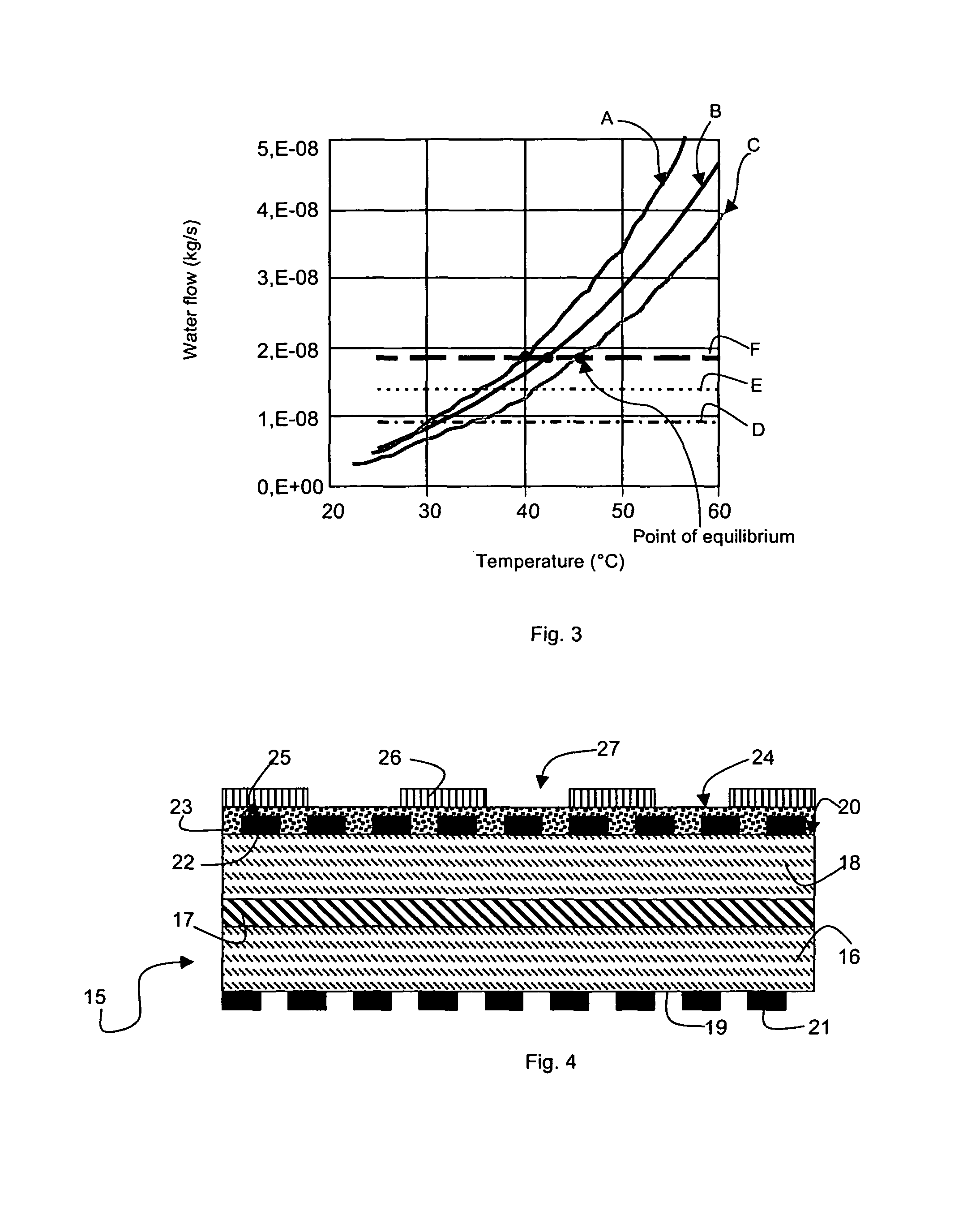
[0021]For illustration purposes, in FIG. 3, curves A, B and C represent the variation of the evacuated water flow in an electrochemical cell versus the temperature of the fuel cell, respectively for three type of heat exchange surfaces. The heat exchange surface corresponding to curve B is a reference heat exchange surface corresponding to the outer surface of a graphite cathode. The heat exchange surfaces corresponding respect...


PUM

PropertyMeasurementUnit
thicknessaaaaaaaaaa
operating currentsaaaaaaaaaa

Abstract

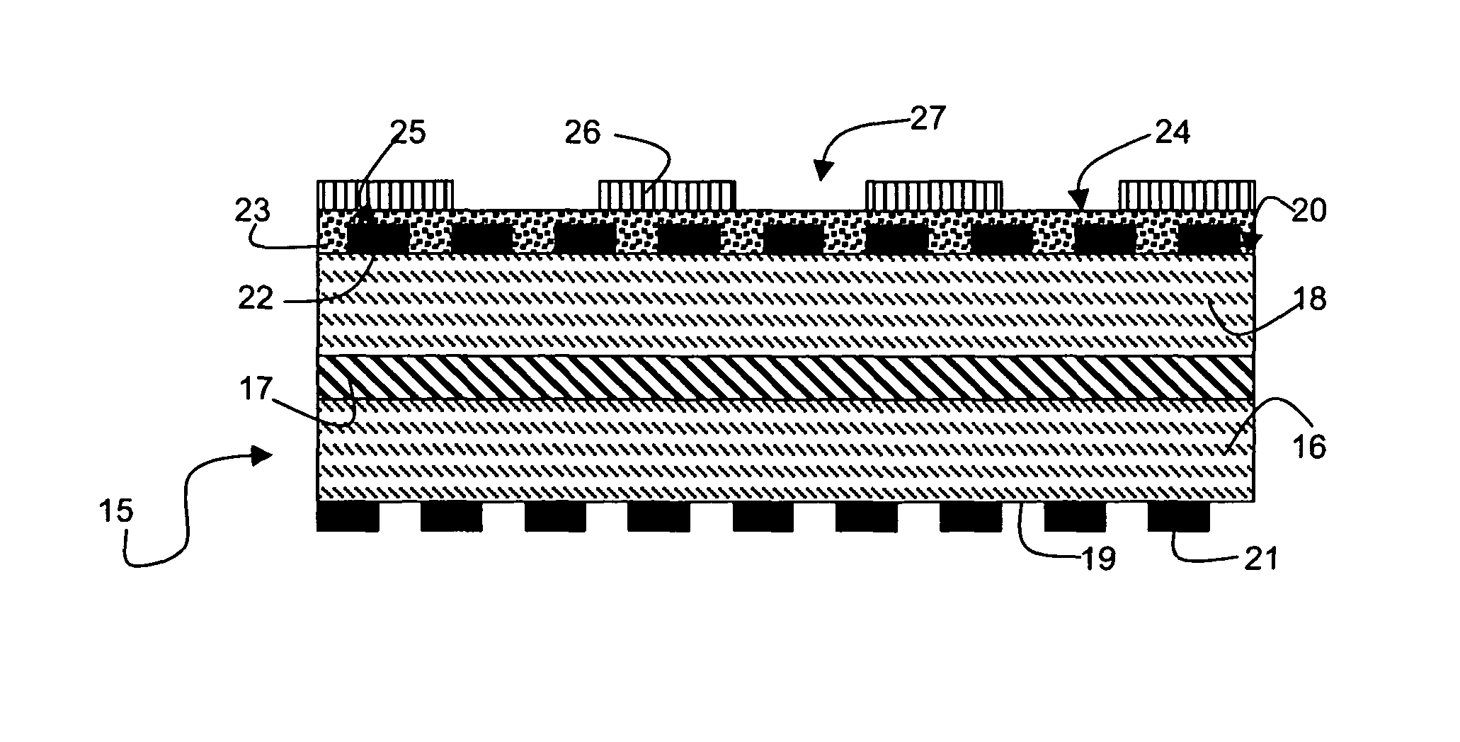
Water produced in a fuel cell is managed and / or regulated by an assembly comprising at least one hydrophobic element and a hydrophilic element. The hydrophilic element is in contact with at least one first area of an outer surface of the cathode. The hydrophobic element covers the whole of a face of the hydrophilic element opposite the outer surface of the cathode and comprises at least one through opening releasing an area of said face of the hydrophilic element.

Description

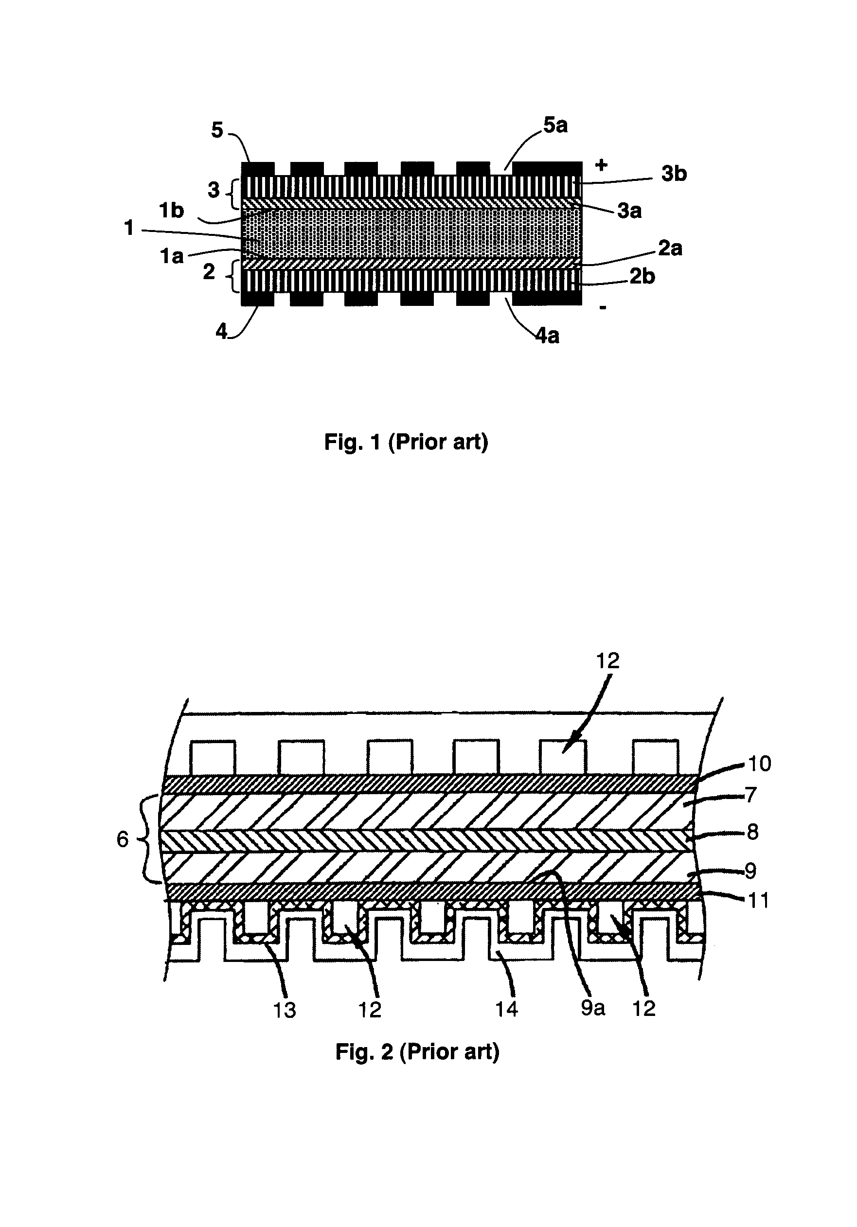
BACKGROUND OF THE INVENTION[0001]The invention relates to a fuel cell and more particularly a fuel microcell comprising:[0002]a successive stacking of an anode, an electrolytic membrane and a cathode,[0003]and an assembly arranged on at least a part of an outer surface of said cathode and comprising at least one hydrophilic element in contact with at least one first area of the outer surface of the cathode and a hydrophobic element covering the whole of a face of the hydrophilic element opposite the outer surface of the cathode.STATE OF THE ART[0004]In the field of fuel cells, two categories of cells exist at present, fuel cells with a filter press type stack and miniature fuel cells produced by means of techniques originating from microtechnology and more particularly by deposition and patterning of thin layers on a substrate.[0005]For example, a basic fuel cell used in a miniature fuel cell is illustrated in FIG. 1. It comprises an electrolytic membrane 1 provided with front and r...

Claims


Application Information

Patent Timeline
Patent Type & Authority Patents(United States)
IPC IPC(8): H01M8/10
CPCH01M8/04119H01M2008/1095Y02E60/50H01M4/8657H01M8/0247H01M8/026
Inventor LAURENT, JEAN-YVESPLISSONNIER, MARCLOCATELLI, DENISFAUCHEUX, VINCENT
Owner COMMISSARIAT A LENERGIE ATOMIQUE ET AUX ENERGIES ALTERNATIVES
Learn More