Duty cycle corrector and clock generator having the same

a technology of clock generator and duty cycle, applied in the direction of pulse automatic control, pulse technique, single output arrangement, etc., can solve the problem of data input/output at exact timing, and achieve the effect of improving the jitter characteristics of d

Inactive Publication Date: 2011-08-09
SK HYNIX INC
View PDF3 Cites 11 Cited by
  • Summary
  • Abstract
  • Description
  • Claims
  • Application Information

AI Technical Summary

Benefits of technology

[0015]Exemplary embodiments of the present invention are directed to providing a Duty Cycle Corrector (DCC) without the use of two clocks with opposite duties and aligned rising edges, and also to improving jitter characteristics of the DCC.

Problems solved by technology

In such a semiconductor device, if a duty ratio of clock is not exactly 50%, a timing mismatch occurs between the rising edge and the falling edge, which makes data not input / output at exact timing.

Method used


Image

  • Duty cycle corrector and clock generator having the same
  • Duty cycle corrector and clock generator having the same
  • Duty cycle corrector and clock generator having the same

Examples


Embodiment Construction

[0030]Hereinafter, the embodiments of the present invention will be described in detail with reference to the accompanying drawings so that the invention can easily be practiced by those skilled in the art to which the invention pertains.

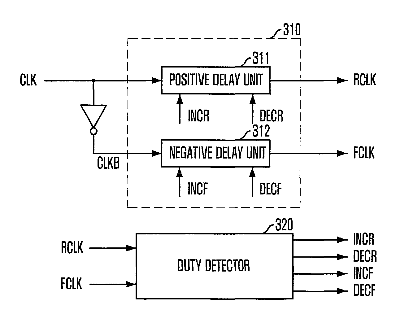
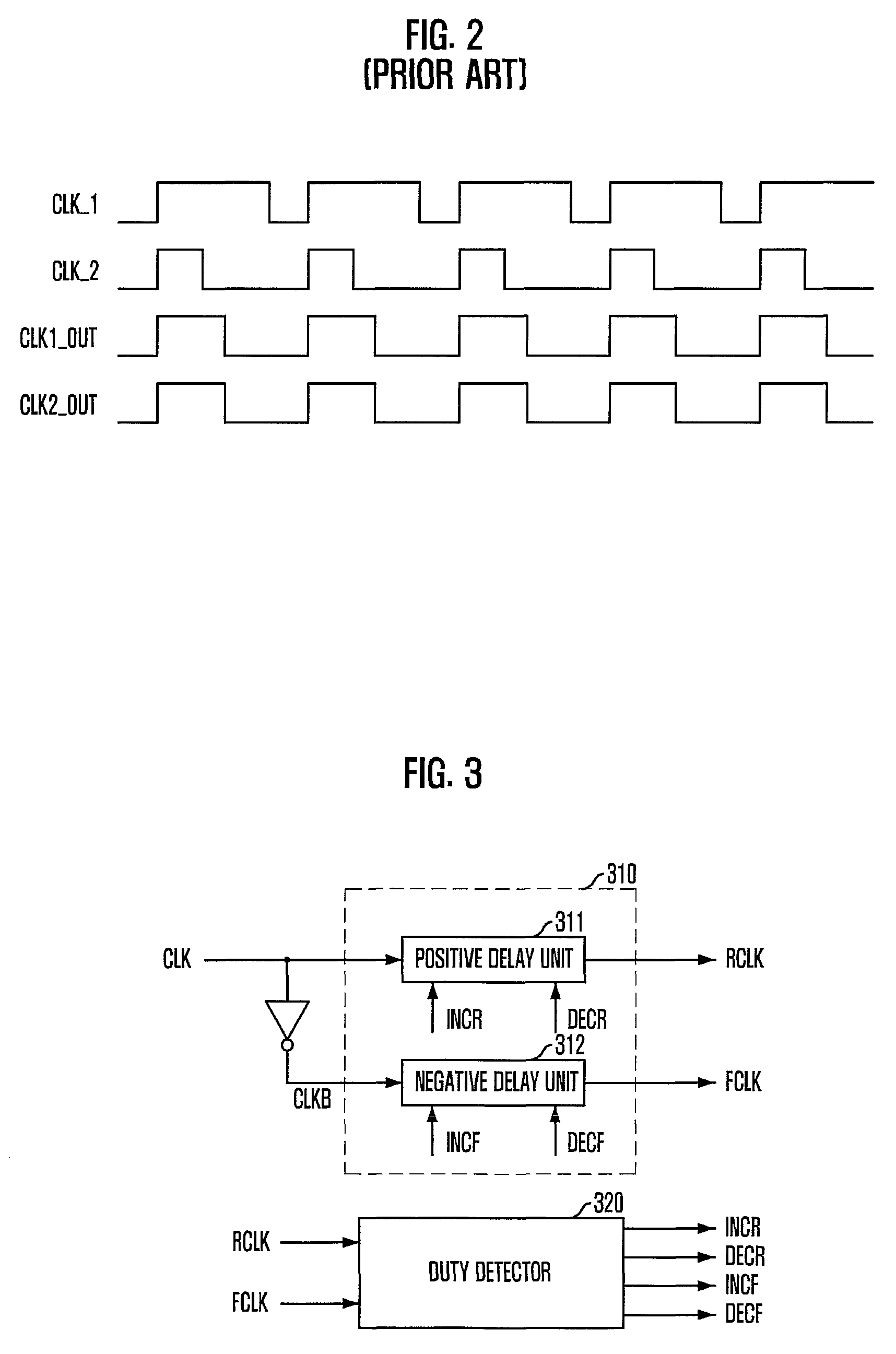
[0031]FIG. 3 is a block diagram illustrating the configuration of a Duty Cycle Corrector (DCC) in accordance with an embodiment of the present invention. As shown, the DCC in accordance with an embodiment of the present invention includes a delay unit 310, a duty detector 320. The delay unit adjusts relative delay values between an input clock CLK and an inverted clock CLKB of the input clock in response to one or more control signals INCR, DECR, INCF and DECF and generates a positive clock RCLK and a negative clock FCLK. The duty detector 320 receives the positive clock RCLK and the negative clock FCLK, detects their duties and generates the one or more control signals INCR, DECR, INCF and DECF.

[0032]To be specific, a rising edge of the negative cl...


PUM


Abstract

A duty cycle corrector includes a delay unit configured to adjust an input clock and an inverted input clock with a delay value controlled in response to one or more control signals and to generate a positive clock and a negative clock, and a duty detector configured to receive the positive clock and the negative clock, to detect duty ratios of the positive clock and the negative clock and to generate the one or more control signals.

Description

CROSS-REFERENCE TO RELATED APPLICATIONS[0001]The present invention claims priority of Korean patent application number 10-2008-0092805, filed on Sep. 22, 2008, which is incorporated by reference in its entirety.BACKGROUND OF THE INVENTION[0002]The present invention relates to a Duty Cycle Corrector (DCC), and more particularly, to a technique for correcting duty cycle with one clock to improve characteristics of DCC.[0003]In semiconductor devices that operate based on a clock, a technique of controlling a duty cycle of the clock exactly is important. A clock duty of 50% indicates that a ‘high’ level interval of a clock signal is identical to a ‘low’ level interval of a clock signal.[0004]For a semiconductor memory device, data should be input / output exactly in synchronization with a rising edge and a falling edge of a clock. In such a semiconductor device, if a duty ratio of clock is not exactly 50%, a timing mismatch occurs between the rising edge and the falling edge, which makes ...

Claims


Application Information

Patent Timeline
Patent Type & Authority Patents(United States)
IPC IPC(8): H03K3/017H03K7/08H03K5/04
CPCH03K3/017H03L7/081H03K5/14
Inventor KU, YOUNG-JUN
Owner SK HYNIX INC
Why Eureka
Try Eureka