Distributed backscattering

a backscattering and distribution technology, applied in the direction of instruments, optical apparatus testing, structural/machine measurement, etc., can solve the problem that inhomogeneities of comparable dimensions or larger than the wavelength may give rise to backscattering

Active Publication Date: 2011-08-09
BRITISH TELECOMM PLC
View PDF175 Cites 28 Cited by
  • Summary
  • Abstract
  • Description
  • Claims
  • Application Information

AI Technical Summary

Benefits of technology

[0012]Typically, the minimum length of fibre required to achieve a sufficient amount of backscattering (that is, so as to form a sufficient strong return signal) has been found to be about 50 or 100 m, although the length may be about 1 km or more. The surprising discovery that distributed backscattering is sufficient in itself to provide return signals means that existing fibre installation can be employed, without requiring a reflector to be introduced specifically for the disturbance sensor. This is likely to be particular

Problems solved by technology

However, inhomogeneities that are of comparable dimensions or larger than the wavelength may give rise to backscattering.
Other me

Method used


Image

  • Distributed backscattering
  • Distributed backscattering
  • Distributed backscattering

Examples


Embodiment Construction

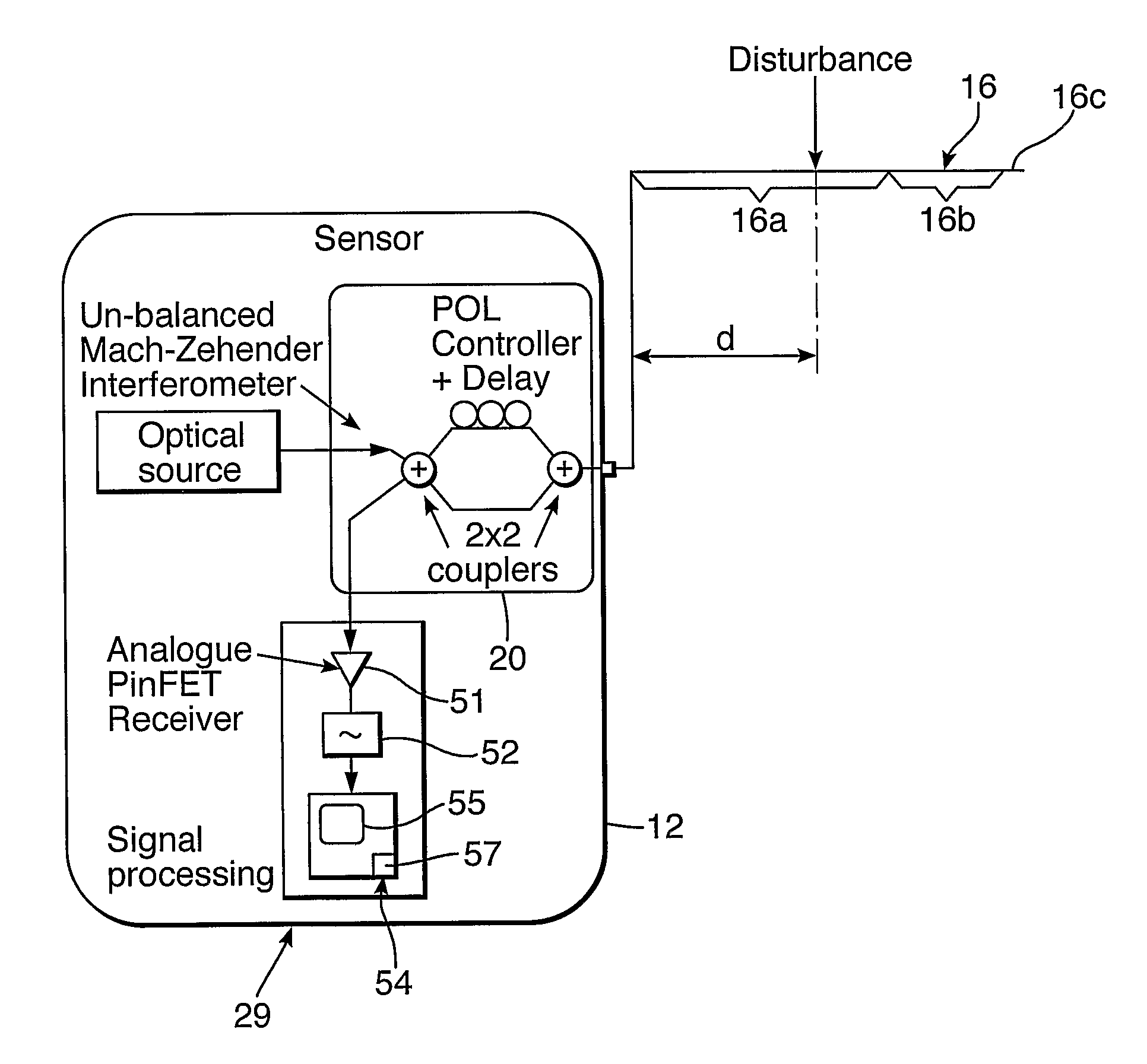
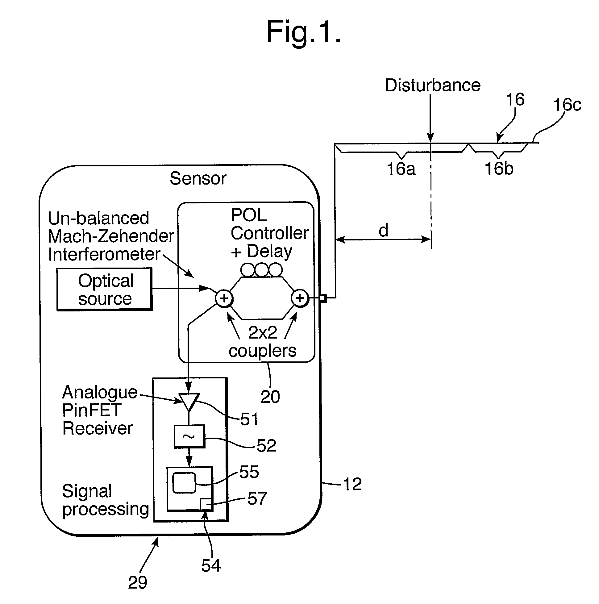
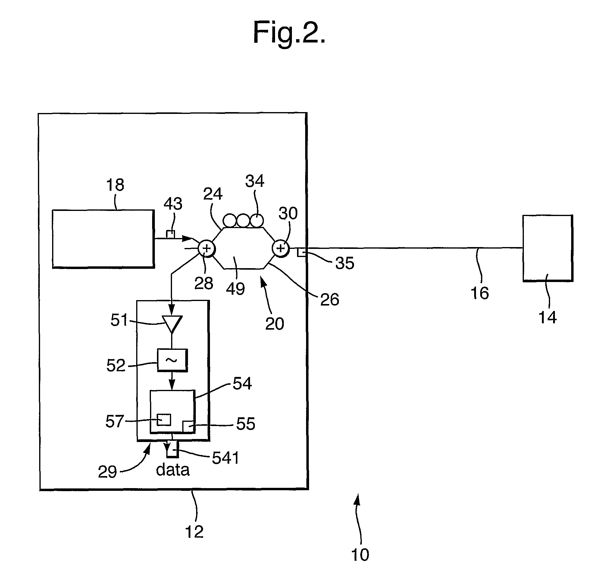
[0024]Light from the optical source is split into two paths in the Mach-Zehender interferometer; one path is connected directly and one goes via an optical delay of several kilometres of standard fibre and polarisation scrambler. Thus the fibre under test conveys two copies of the source signal, one delayed by an amount “D” relative to the other. The source signals are backscattered in a continuous fashion as they propagate from the source along the fibre, the backscattered signals being returned towards the source after they have traveled through a portion of the fibre. For signals that had propagated beyond the disturbance point, the phase, polarisation and amplitude of the signals will be perturbed by the disturbance in both the forward and reverse directions of propagation. On returning to the interferometer the differential delay “D” is effectively un-done for one pair of propagating signals. Optical interference takes place at the 2×2 port coupler nearest the receiver creating...


PUM


Abstract

The present invention relates to a method for detecting or inferring a physical disturbances on a communications link, in particular by using distributed backscattering. The method includes the steps of: transmitting test signals onto a link; receiving test signals returned from a remote portion of the link; performing a function on the returned test signals; and in dependence on at least one characteristic of the combination signal, inferring the presence of a disturbance. The test signal are returned by a process Rayleigh backscattering along the fibre, so existing fibre installations can be used without requiring a mirror to be specifically introduced.

Description

[0001]This application is the US national phase of international application PCT / GB2005 / 003680 filed 26 Sep. 2005 which designated the U.S. and claims benefit of GB 0421747.7, dated 30 Sep. 2004, the entire content of each of which is hereby incorporated by reference.BACKGROUND[0002]1. Technical Field[0003]The present invention relates to detecting or inferring physical disturbances on a communications link, in particular by using distributed backscattering.[0004]2. Related Art[0005]It is known to detect disturbances in a data communications link by causing signals from one data link to interfere with signals which have traveled along another data link. However, this normally requires the signals to travel coherently along the data link, which requirement is not always possible to achieve.BRIEF SUMMARY[0006]According to one aspect of the present invention, there is provided a method of monitoring an optical transmission link to detect a physical disturbance of the link, the method i...

Claims


Application Information

Patent Timeline
IPC IPC(8): G01N21/00G01M11/00H04B10/071
CPCG01M11/3181H04B10/071
Inventor SIKORA, EDMUND S RHEALEY, PETER
Owner BRITISH TELECOMM PLC
Why Eureka
Try Eureka