Method and a system for filling a refrigeration system with refrigerant

a refrigeration system and refrigerant technology, applied in gas cycle refrigeration machines, vehicle heating/cooling devices, light and heating apparatuses, etc., to achieve the effect of reducing the cost of us

Inactive Publication Date: 2011-03-01
AGRAMKOW FLUID SYST
View PDF11 Cites 0 Cited by
  • Summary
  • Abstract
  • Description
  • Claims
  • Application Information

AI Technical Summary

Benefits of technology

[0013]This eliminates the known drawback of filling with gas that there is a so-called “dead” amount of gas in the connecting line between the internal refrigerant source and the system, which may vary much depending on temperature and pressure.
[0015]The great advantage of the method is that it is possible to select between filling with liquid or gas in an expedient performance of the method comprising the components necessary for this. This saves construction of various systems, and an advantage in terms of use is achieved by combining the two states in a system.

Problems solved by technology

The problem of the filling of CO2 is that it is very volatile in the usual temperature range between 10 and 50° C., which constitutes the “over-critical” temperature range, whose range is above 31.8° C., where CO2 cannot be compressed to a liquid, but is in gas form.
Filling therefore involves the problem that the refrigerant may be either liquid or gas depending on the temperature.
This is not the case with CO2, where the critical point is 31° C. Therefore, it is not possible to condition CO2 in this known system, as the pressure in the container cannot get below the critical point and thereby cause CO2 to assume liquid form.

Method used


Image

  • Method and a system for filling a refrigeration system with refrigerant
  • Method and a system for filling a refrigeration system with refrigerant

Examples


Embodiment Construction

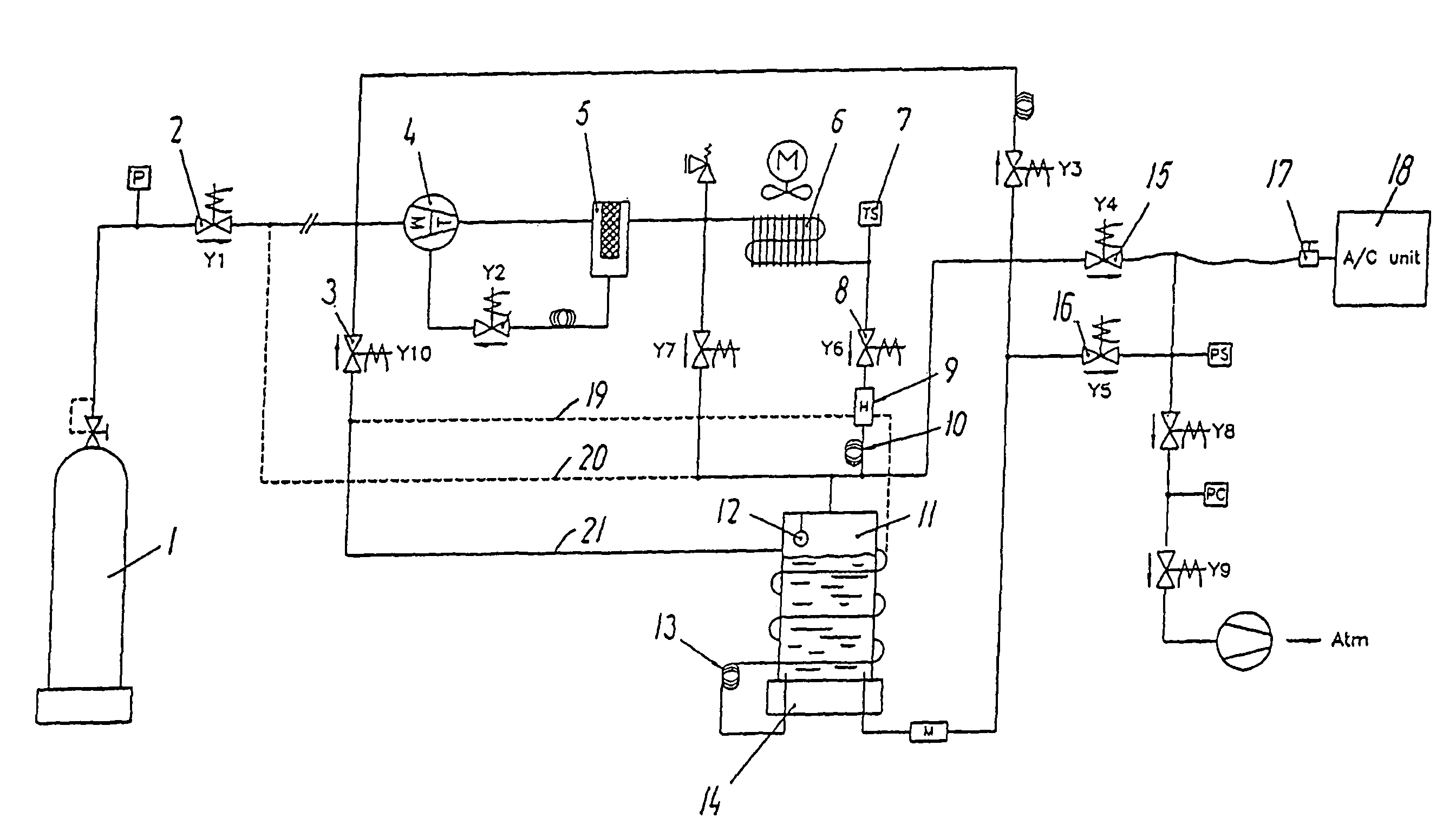
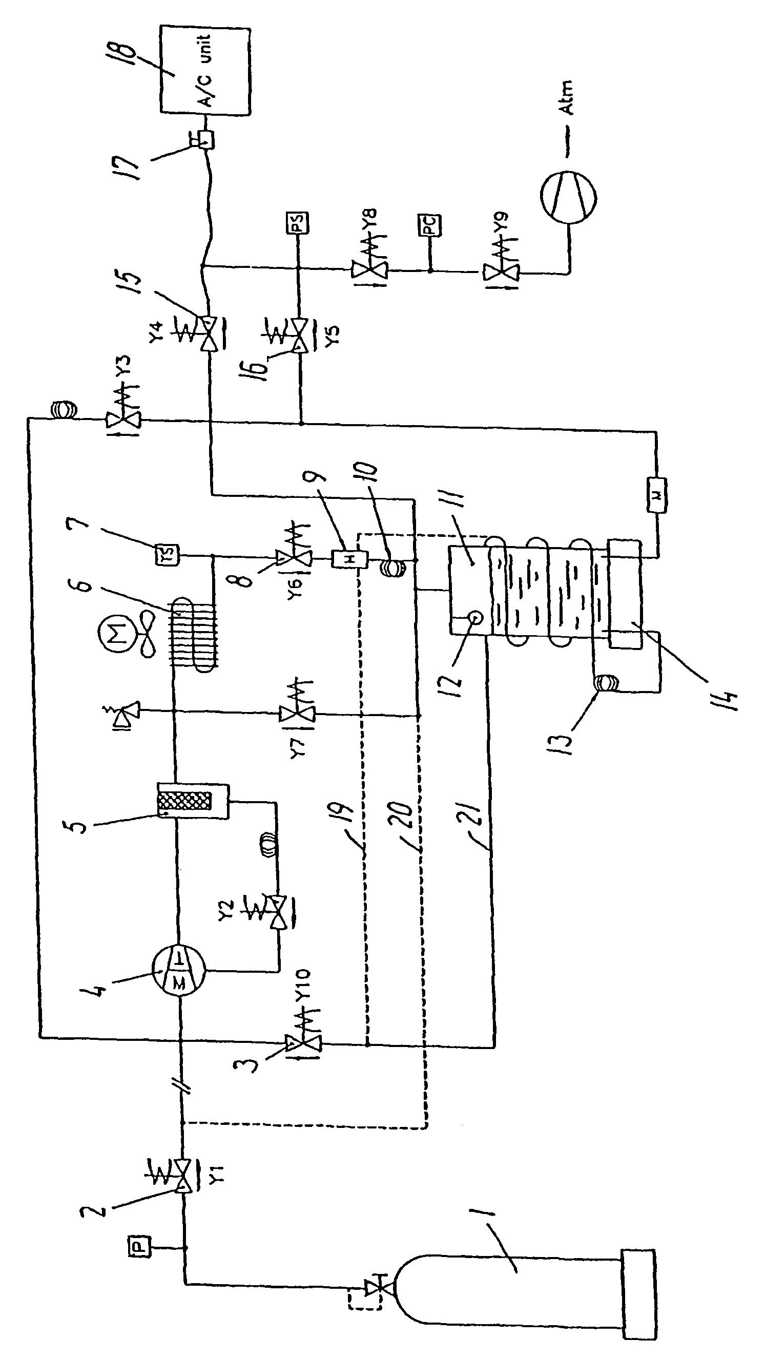
[0019]An example of a system according to the invention is shown in the drawing, said system comprising a connected external pressure bottle 1, from which the CO2 required for the filling is sucked out by means of a compressor 4.

[0020]Further, an oil filter 5, a gas cooler 6 and an internal pressure bottle 11 with a level sensor 12 and a weighing unit 14 as well as a pressure reduction unit 13, a magnetic valve 3 and a return line to the low pressure side of the compressor are mounted on the pressure side of the compressor 4.

[0021]Moreover, a pipe connection is provided between the internal pressure bottle 11 via a valve 15, a coupling 17 to the connected air conditioning system 18 which is to be filled with refrigerant.

[0022]The method will now be described with filling of CO2 in gas form.

[0023]The system is connected to the internal pressure bottle 1 with CO2 and the refrigeration system 18 via a coupling 17.

[0024]The valve 2 is opened, the compressor 4 is started, and CO2 is suck...


PUM


Abstract

According to the invention, there is described a method and a system which use a compressor (4) for filling CO2 into an air conditioning system (18) via an oil filter (5) and a gas cooler (6). CO2 may be pumped to an internal pressure container (11), and from there the air conditioning system (18) may be filled with CO2 in gas form via valves (15). The fill system may additionally include a heat exchanger (9), so that a temperature may be controlled in the pressure container (11) so that it does not exceed 31.8 C, whereby CO2 may be filled into the air conditioning system (18) in liquid form.

Description

THE PRIOR ART[0001]The invention relates to a method of filling refrigerant, such as CO2, into a refrigeration system, such as an air conditioning system in a vehicle, from an external pressure bottle to an internal pressure bottle in which the filled amount of CO2 is recorded prior to the filling, as well as a system for performing the method.[0002]Systems for filling refrigerant, such as CO2, from an external pressure bottle into an air conditioning system are known.[0003]The problem of the filling of CO2 is that it is very volatile in the usual temperature range between 10 and 50° C., which constitutes the “over-critical” temperature range, whose range is above 31.8° C., where CO2 cannot be compressed to a liquid, but is in gas form.[0004]Filling therefore involves the problem that the refrigerant may be either liquid or gas depending on the temperature. This necessitates systems which use either liquid or gas.[0005]WO 89 / 03963 discloses a system for the filling of refrigerants, ...

Claims


Application Information

Patent Timeline
Patent Type & Authority Patents(United States)
IPC IPC(8): F25B45/00
CPCB60H1/00585F25B9/008F25B45/00F25B2345/001F25B2309/06
Inventor CORDING, LOUIS
Owner AGRAMKOW FLUID SYST
Why Eureka
Try Eureka