
Portable short electric arc processing system

a processing system and electric arc technology, applied in the field of short electric arc technology, can solve the problems of poor safety in existing technologies, inconvenient use, heavy labor intensity, etc., and achieve the effect of excellent safety and less labor intensity

Inactive Publication Date: 2018-09-18
XINJIANG SHORT ELECTRIC ARC SCI & TECHNICAL DEV CO LTD
View PDF12 Cites 0 Cited by
  • Summary
  • Abstract
  • Description
  • Claims
  • Application Information

AI Technical Summary

Benefits of technology

The system achieves convenience in use, reduces labor intensity, and enhances safety during short electric arc processing, enabling efficient and safe operation.

Problems solved by technology

In the realization of the present invention, the inventor found the defects of inconvenient use, heavy labor intensity and poor safety in the existing technologies.

Method used


Image

  • Portable short electric arc processing system
  • Portable short electric arc processing system
  • Portable short electric arc processing system

Examples


first embodiment

[0124]The a water air mixing system for a portable pneumatic circulation tool: Y-shaped two-way fitting 44e, water air mixture 45e, Y-shaped quick connector 46e, threaded barrel 47e, water air mixture 48e, air pump and water pump. Refer to 31A2025-1 and a pneumatic circulation tool as shown in FIG. 6.

[0125]Compressed air provided by the air pump is connected to the Y-shaped quick connector 44 through an air pipe. The Y-shaped quick connector 44e provides a discharged or used air for the Y-shaped quick connector 46e of the water air mixture 45e through an air pipe and it also provides a working medium of water air mixture through a water air nipple 48e so as to recycle the used air. Water goes through T-shaped quick connector 45e through water pipe and is distributed to two couples of Y-shaped quick connector 46e with water air mixture 48e. Quick connector 46e and water air mixture 48e are connected through a threaded barrel 47e. A Control valve may be used for adjusting an inflow w...

second embodiment

[0126]The a water air mixing system for a movable pneumatic circulation device: including water pump, air pump, water pipe, air pipe, water air mixing device, and connectors. Refer to the figure for a circulation device.

[0127]The Cathode shield 13e is equipped with a water air mixing device and adjustment device. The water air mixing device can be adjusted up / down and up / down according work needs.

6. Hanger:

[0128]As shown in FIG. 5, a hanging bracket for a short-electric arc discharging processing toolhanger comprises a rotatable chassis 1d, a stand 4d, an adjustable cantilever 3d, a hanging means 11d, a winch 16d, a tension spring, a wire rope or reinforced fireproof rope, a pulley 25d and pulley yoke 28d, a safety buckle 6d, a hanging ring 9d, a supporting leg assembly 23d and a locking pin 24d.

[0129]The hanger comprises: a rotatable chassis 1d comprising a base 22d and an upper wheel; the base 22d is connected with the chassis by means of four bolts 31d and elastic washers 32d a...


PUM

PropertyMeasurementUnit
input voltageaaaaaaaaaa
voltageaaaaaaaaaa

Abstract

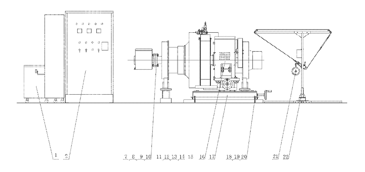
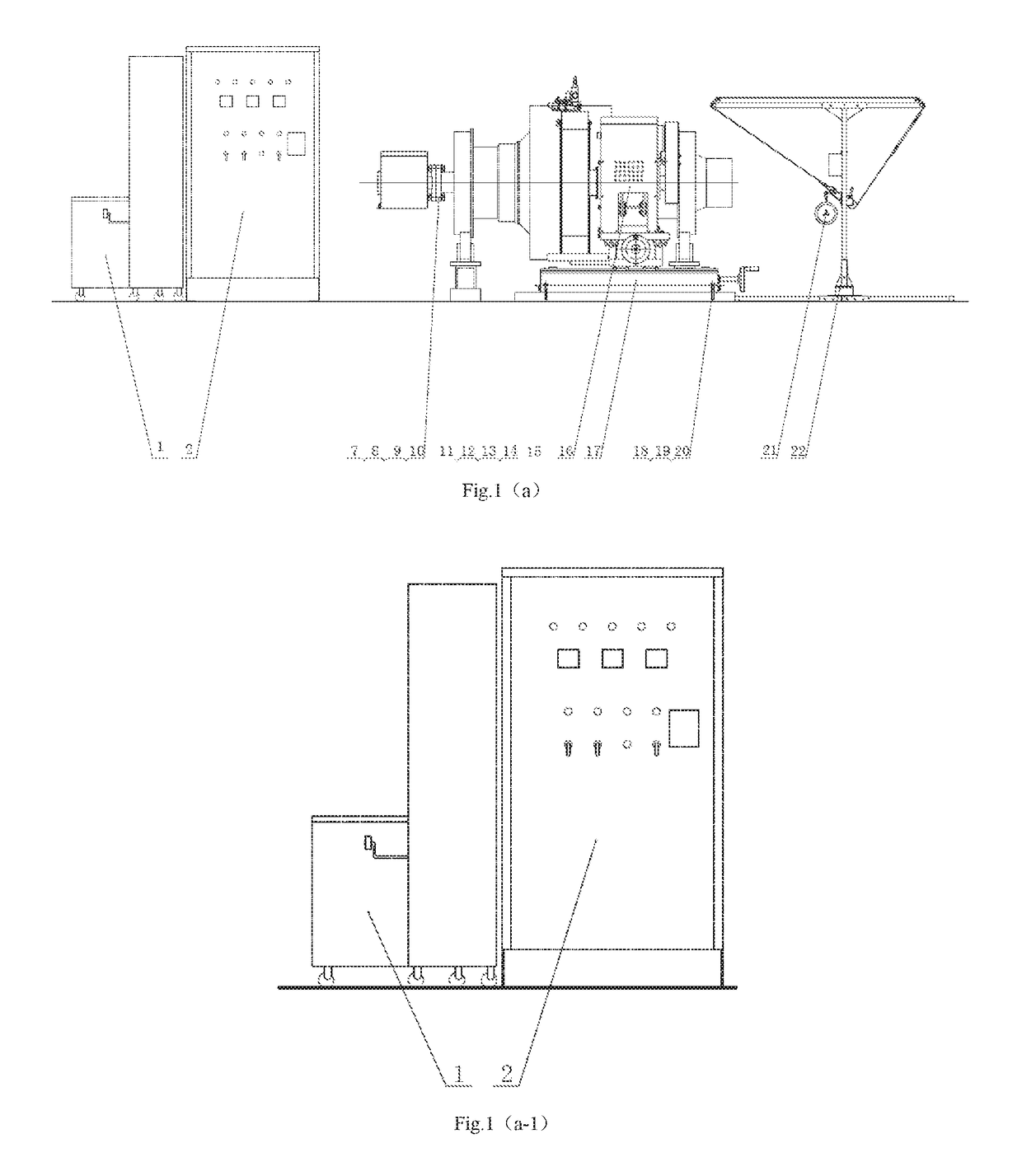
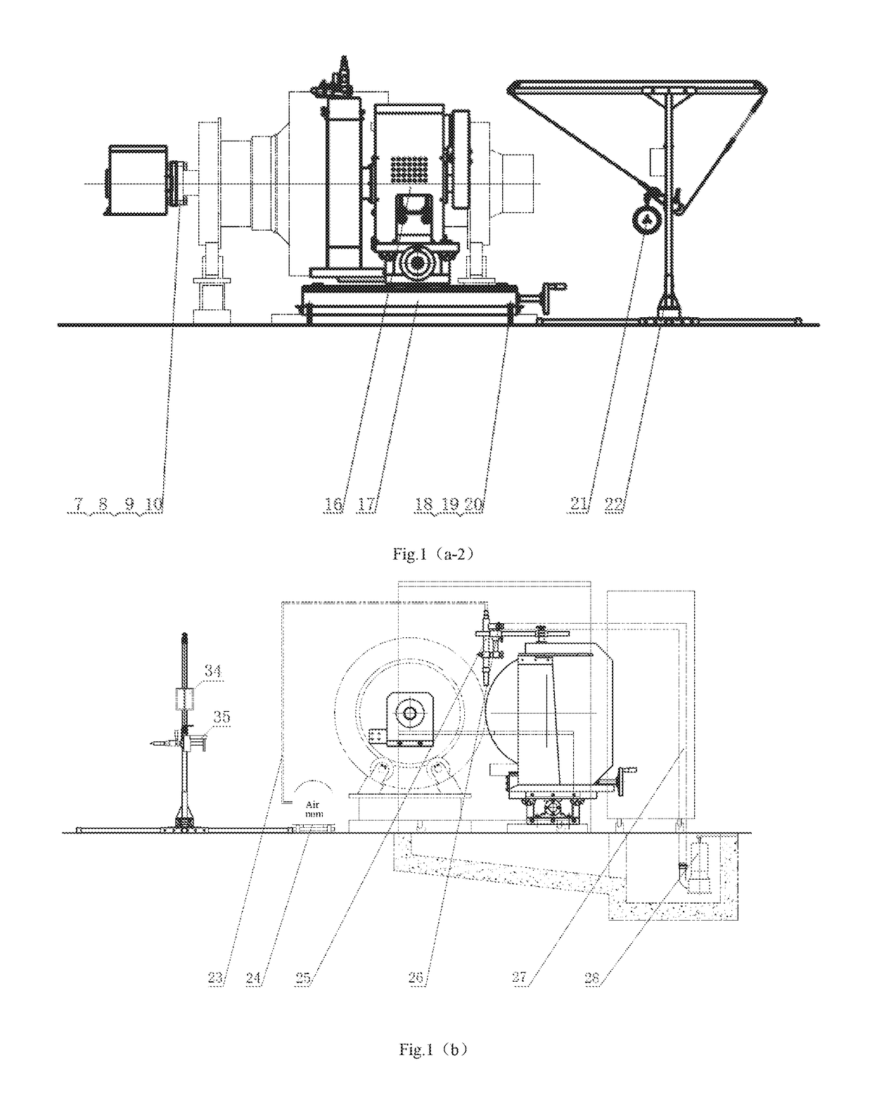
A portable movable discharge processing system by short electric arc, including a power supply cooling water tank, a short electric arc cutting power supply, a ring current device a feeding mechanism, a hanging bracket and a pneumatic ring current tool mounted on the hanging bracket, which are successively and cooperatively mounted on a horizontal plane; an air compressor and a sewage pump, which are successively connected to the feeding mechanism; a self-priming pump and a movable short-electric arc cutting device control cabinet, which are successively connected to the air compressor; an anode device which is connected to the movable short-electric arc cutting device control cabinet through an anode cable; a cathode device which is connected to the movable short-electric arc cutting device control cabinet through a cathode cable; and a water pump which is connected to the anode device through a pipeline.

Description

[0001]This is a U.S. national stage application of PCT Application No. PCT / CN2015 / 000590 under 35 U.S.C. 371, filed Aug. 14, 2015 in Chinese, claiming the Chinese priority application No. 201410632093.X filed Nov. 11, 2014, which are all hereby incorporated by reference.TECHNICAL FIELD[0002]The present invention refers to short electric arc technology field, particularly to a portable Short Electric Arc Processing System.BACKGROUND OF THE INVENTION[0003]Discharge of short electric arc refers to an effectively controlled discharge cluster phenomenon with specific current, voltage wave, frequency, amplitude and discharge mode that is generated by scientific mechanical motion and electric action in the action of air-liquid medium.[0004]Short electric arc cutting technology refers to an electric cutting method to corrode metal and non-metal conductive materials by the simulated short electric arc discharge cluster of sparkle discharge cluster produced between two electrodes in the mediu...

Claims


Application Information

Patent Timeline
Patent Type & Authority Patents(United States)
IPC IPC(8): B23H1/02B23K9/09B23H11/00
CPCB23H1/02B23K9/09B23H11/00B23H1/022B23H1/00B23K9/013B23K9/32
Inventor ZHOU, BISHENG
Owner XINJIANG SHORT ELECTRIC ARC SCI & TECHNICAL DEV CO LTD
Learn More