Polarization conversion element, polarization conversion optical system and image projecting apparatus

a technology of optical system and polarization conversion element, which is applied in the field of polarization conversion element, polarization conversion optical system and image projecting apparatus, can solve the problems of difficult to form an optical system which combines the separated beams, the polarization conversion element can be thin, and the polarization conversion element is large, so as to reduce the number of bonding times in increase the productivity of manufacturing the polarization conversion elemen

Inactive Publication Date: 2011-08-09
RICOH KK
View PDF41 Cites 44 Cited by
  • Summary
  • Abstract
  • Description
  • Claims
  • Application Information

AI Technical Summary

Benefits of technology

[0017]The present invention solves one or more of the problems in the conventional technologies. According to an embodiment of the present invention, there is provided a polarization conversion element, a polarization conversion optical system using the polarization conversion element, and an image projecting apparatus using the polarization conversion optical system in which the number of bonding times in manufacturing the polarization conversion element is decreased and productivity in manufacturing the polarization conversion element is increased.
[0023]According to embodiments of the present invention, in a polarization conversion element, a polarization separation section separates an input light flux into transmission light (P polarization) and reflection light (S polarization) and also reflects the reflection light reflected from an adjacent polarization separation section in the same direction as that of the transmission light. Therefore, a reflection film (separation film) which is needed only for reflection in a conventional polarization conversion element is not required. Consequently, almost the same effect as that in the conventional polarization conversion element can be obtained by disposing only the polarization separation sections having the same pitch as that of a lens in a lenticular lens array or a fly-eye-lens, and the pitch can be twice as many as that in the conventional polarization conversion element. With this, productivity can be increased. In addition, since the polarization separation section can be disposed parallel to the phase modulation section, the polarization separation section can be closely disposed on the phase modulation section. Therefore, the polarization separation section can be disposed at high accuracy and manufacturing the polarization conversion element becomes easy.
[0024]In addition, a polarization conversion optical system having low losses of light quantity can be formed by combining the polarization conversion element with lenticular lens arrays or fly-eye lenses. Further, an image projecting apparatus can be realized by only using the above polarization conversion element or the above polarization conversion optical system without changing the conventional optical system.

Problems solved by technology

In the second method, since the reflection by the mirrors is used, the conversion can be efficiently performed regardless of wavelengths; however, since illumination beams from the image projecting apparatus have a certain thickness, the size of the polarization conversion element which uses the mirrors becomes large and also it is not easy to form an optical system which combines the separated beams.
When the polarization conversion element is divided into many pieces and the many pieces are arrayed, the polarization conversion element can be thin; however, arraying the mirrors is logically possible, but actually difficult.
Therefore, many man-hours are required.
As shown in FIG. 29B, the polarization separation film can also work as the reflection film; however, two films (surfaces) are also needed for one lens in the fly-eye lens, and the number of bonding times of glass plates cannot be reduced.

Method used


Image

  • Polarization conversion element, polarization conversion optical system and image projecting apparatus
  • Polarization conversion element, polarization conversion optical system and image projecting apparatus
  • Polarization conversion element, polarization conversion optical system and image projecting apparatus

Examples


Embodiment Construction

[0057]Next, referring to the drawings, embodiments of the present invention are described in detail.

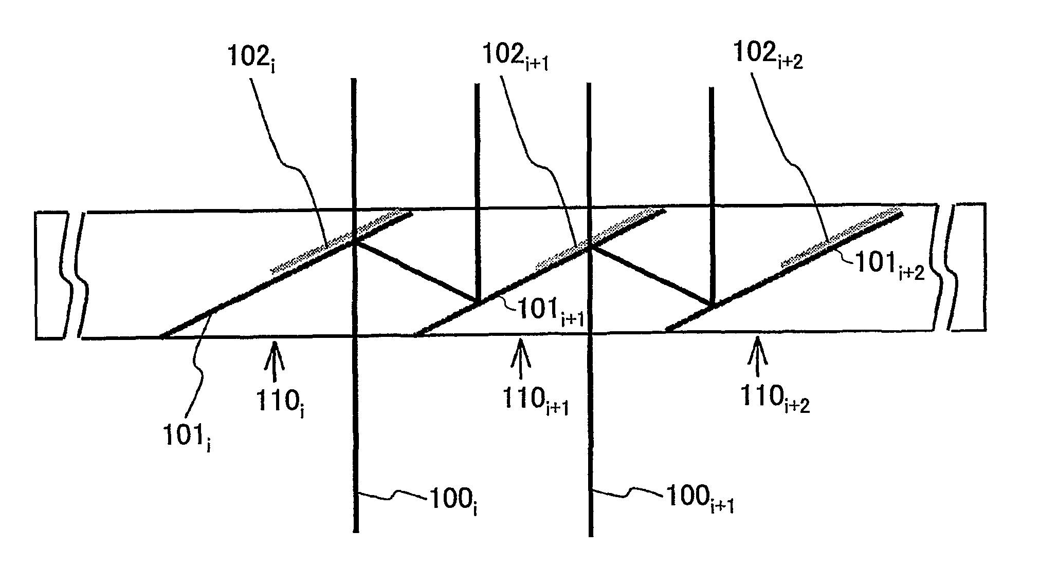
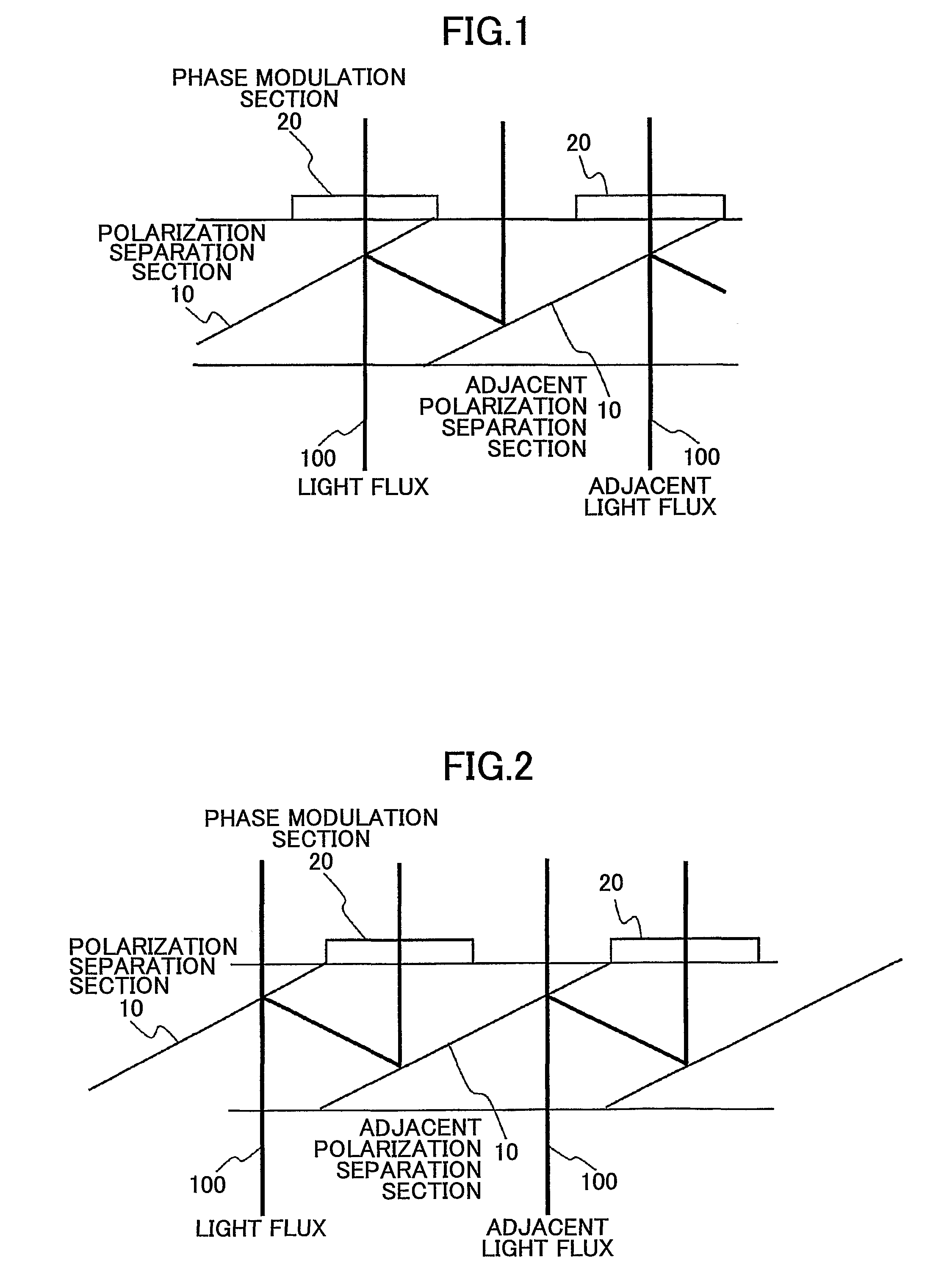
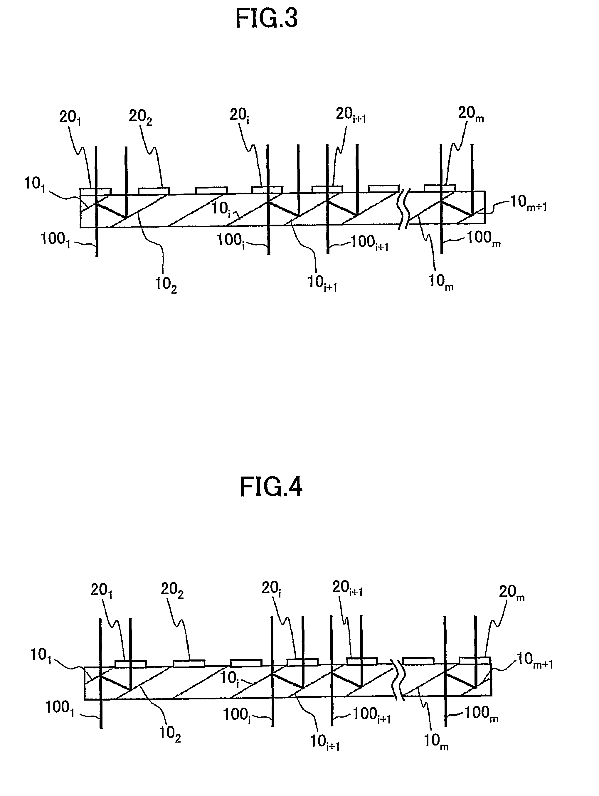
[0058]FIG. 1 is a diagram showing a structure of a polarization conversion element according to an embodiment of the present invention. The polarization conversion element according to the embodiment of the present invention provides plural polarization separation sections 10 and plural phase modulation sections 20. A light flux 100 is input to each polarization separation section 10 and is separated into transmission light and reflection light whose polarization direction is different from that of the transmission light. When the polarization separation section 10 is formed by a general multi-layer polarization separation film, the transmission light becomes P polarization and the reflection light becomes S polarization. The reflection light reflected at the polarization separation section 10 is reflected again at an adjacent polarization separation section 10 and becomes a light flu...


PUM


Abstract

A polarization conversion element having plural polarization separation sections and plural phase modulation sections is disclosed. A light flux is separated into transmission light (P polarization) and reflection light (S polarization) by being input to a polarization separation section. The reflection light reflected at the polarization separation section is output in the same direction as that of the transmission light by being reflected again at an adjacent polarization separation section at a different position from a position where a light flux is input to the adjacent polarization separation section. The phase modulation section is disposed on an optical path of the transmission light or the reflection light and output light becomes the same polarization.

Description

TECHNICAL FIELD[0001]The present invention generally relates to a polarization conversion element which is used in an image projecting apparatus of transmission type or reflection type, a polarization conversion optical system which uses the polarization conversion element, and an image projecting apparatus which uses the polarization conversion optical system.BACKGROUND ART[0002]In a liquid crystal image forming element which is used in an image projecting apparatus, a polarization component of one direction is only effectively utilized and a polarization component of the other direction orthogonal to the above direction causes degradation of contrast. Therefore, the polarization direction is controlled by disposing a polarizer at the front stage and the back stage of the liquid crystal image forming element. However, light beams emitted from a light source are non-polarization beams whose polarization directions are not the one direction. Therefore, when the polarization component...

Claims


Application Information

Patent Timeline
Patent Type & Authority Patents(United States)
IPC IPC(8): G02B5/30G02B27/28
CPCG02B27/285H04N5/7416G03B33/12G03B21/2073H04N9/3167G02B5/30
Inventor MAEDA, IKUOFUJITA, KAZUHIRO
Owner RICOH KK
Why Eureka
Try Eureka