
Backscatter interrogator reception method and interrogator for a modulated backscatter system

a backscatter system and reception method technology, applied in the field of backscatter interrogator reception method and interrogator for a modulated backscatter system, can solve the problem of strong so-called inband interference, and achieve the effect of improving the receiver sensitivity of the interrogator

Inactive Publication Date: 2011-08-09
SONY DEUT GMBH
View PDF17 Cites 22 Cited by
  • Summary
  • Abstract
  • Description
  • Claims
  • Application Information

AI Technical Summary

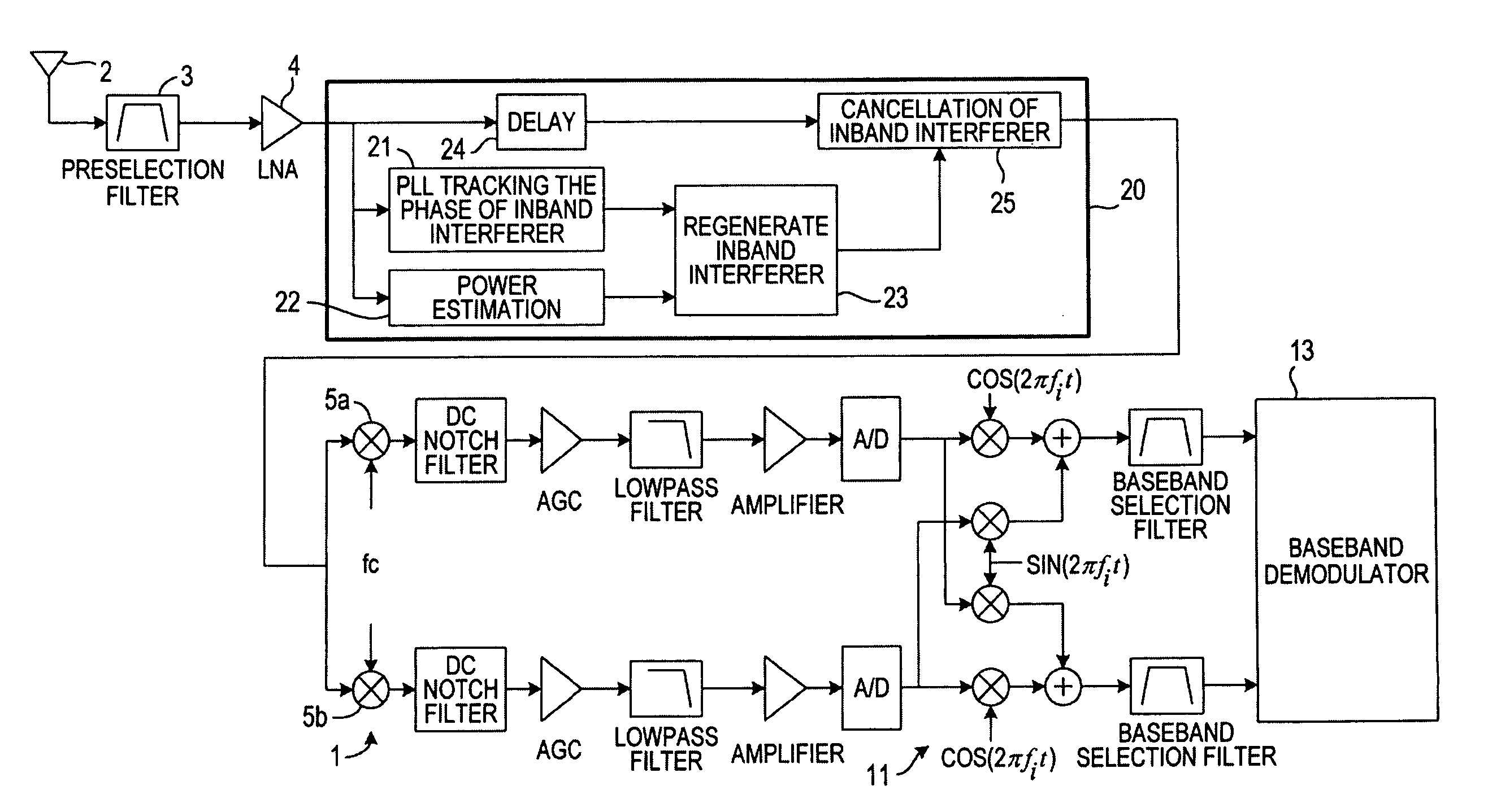
Benefits of technology

[0010]Accordingly, it is an object of the present invention to overcome the problems mentioned above by providing an interrogator for use in a modulated backscatter system wherein the performance of the receiver sensitivity of the interrogator is improved.
[0011]The present invention proposes a novel idea for reducing the effect of the leakage of the interrogating RF waveform—called inband interferer—allowing to achieve an improved receiver sensitivity.
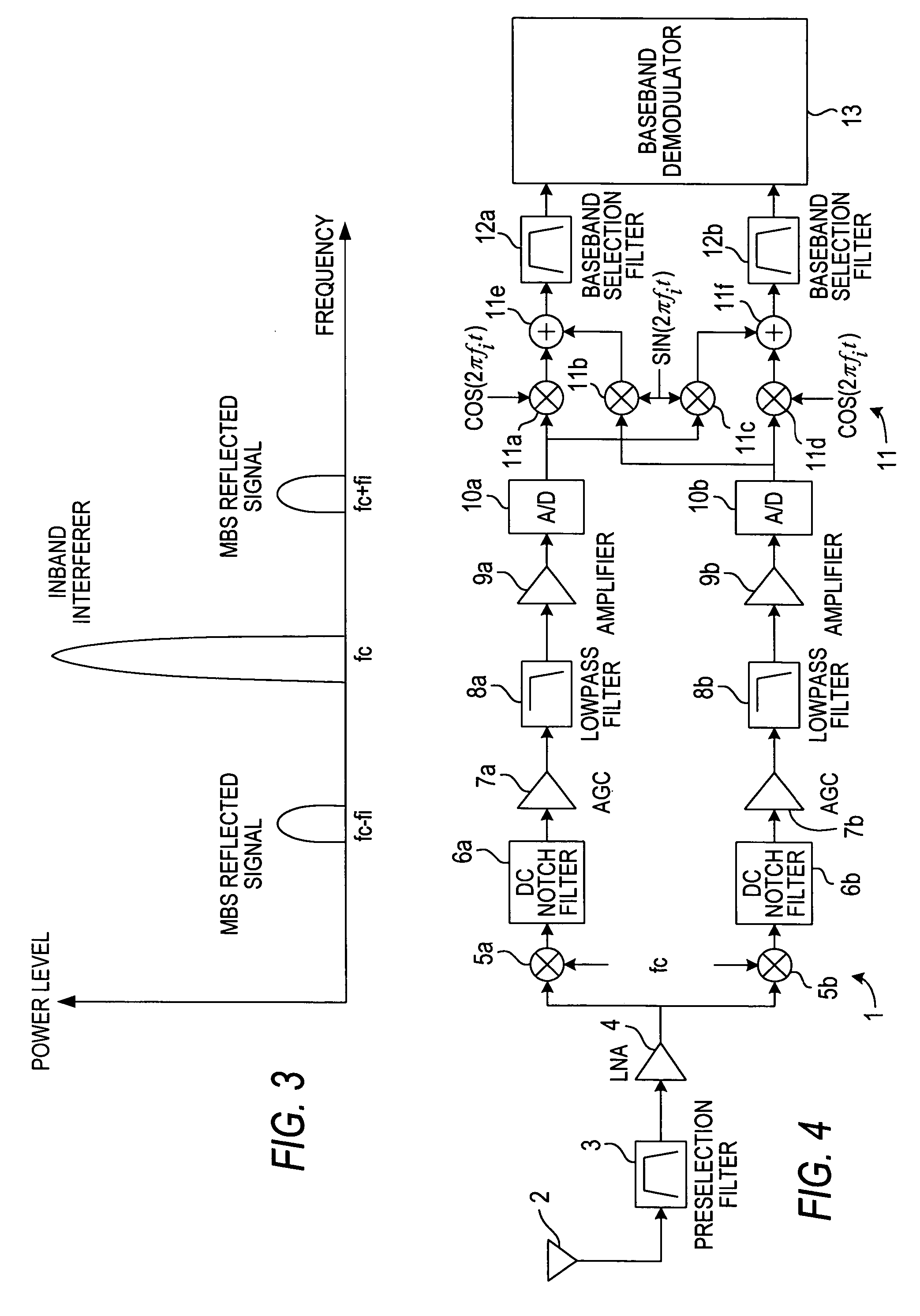
[0012]Since inband interferers always exist in modulated backscatter systems and are much stronger than the received backscatter signal itself, it is—according to a first aspect of the present invention—proposed to adopt the principle of a Phase Locked Loop (PLL) in order to track the phase and amplitude of the strong inband interferer and to generate a cancellation signal that is equal in amplitude and 180° out of phase with the inband interferer. After that, this generated cancellation signal is combined with the received signal to implement an inband interferer cancellation before the received signal is forwarded to the next stage in which the signal is finally demodulated in order to retrieve the data transmitted from the tag. By using this technique, the power level of inband interferer is significantly reduced and an improved receiver sensitivity can be obtained.

Problems solved by technology

One problem arising with the use of backscatter communication is the appearance of strong so-called inband interferer.

Method used


Image

  • Backscatter interrogator reception method and interrogator for a modulated backscatter system
  • Backscatter interrogator reception method and interrogator for a modulated backscatter system
  • Backscatter interrogator reception method and interrogator for a modulated backscatter system

Examples


Embodiment Construction

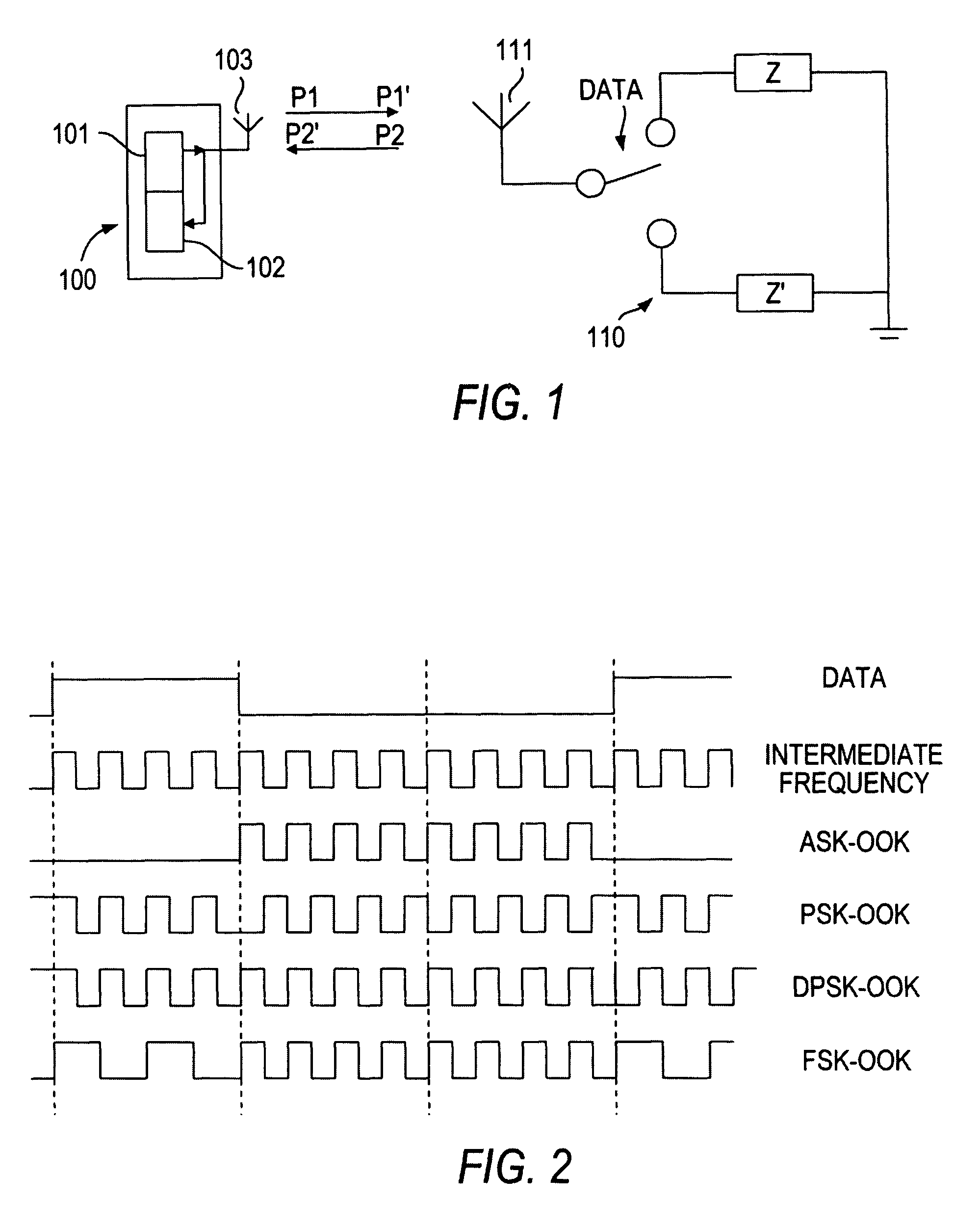
[0042]The principles of modulated backscatter communication have already been explained with reference to FIG. 1. Again, in order to achieve a modulation of the signal P1 emitted from the interrogator 100, the load impedance of the antenna 111 of the tag 110 is changed for example between values representing the data signals “1” and “0”. From the point of view of the interrogator 100, the interrogating radio frequency waveform reflected by the tag 110 is switched in its amplitude (and / or phase) between those two values. When the switch is closed the antenna 111 becomes the electrical equivalent of a single half-wave length antenna that reflects a portion of the power; when the switch is open, the antenna 111 becomes the electrical equivalent of a two quarter wave length antenna that reflects very little of the power. This effect corresponds to an amplitude-shift-keying (ASK) modulation with a small modulation depth.

[0043]The modulated reflected signal P2 is called the MBS signal, wh...


PUM


Abstract

In a backscatter interrogator reception method, a continuous carrier signal with a frequency fc is sent from an interrogator to a tag device over a wireless link, the tag device transmits data to the interrogator using a modulated backscatter signal, and the received modulated backscatter signal is demodulated by the interrogator to retrieve the data transmitted from the tag device. According to the present invention, the interrogator estimates the phase and the amplitude of an inband interferer signal contained in the received modulated backscatter signal, generates a cancellation signal having the opposite phase and the same amplitude as the estimation of the inband interferer signal, and combines said cancellation signal with the received backscatter signal in order to reduce the influence of the inband interferer signal. In addition, a two-stage interferer cancellation scheme is proposed.

Description

BACKGROUND OF THE INVENTION[0001]1. Field of the Invention[0002]The present invention relates to a method for backscatter interrogator reception as well as to an interrogator for use in a modulated backscatter system (MBS).[0003]2. Description of the Related Art[0004]Modulated backscatter systems are known in the art and are the basis for the recently developed so-called radio frequency identification (RFID) systems. These RFID systems are for example used for identifying and / or tracking equipment, inventory, persons or animals. RFID systems are radio communication systems that allow communication between a radio transceiver, called an interrogator, and at least one so-called tag. In an RFID system the interrogator communicates with the tag by transmitting an unmodulated radio signal which is received, modulated and transmitted back by the tag to the interrogator.[0005]The general idea underlying a modulated backscatter system is shown in FIG. 1. Similar to the field of radar techno...

Claims


Application Information

Patent Timeline
Patent Type & Authority Patents(United States)
IPC IPC(8): H03D1/04H03D1/06H04B1/10G06K7/00H04B1/52
CPCG06K7/0008H04B1/525
Inventor WANG, ZHAOCHENGBOHNKE, RALFREBMANN, JOCHEN
Owner SONY DEUT GMBH
Learn More