Method and surgical navigation system for creating a recess to receive an acetabulum

a technology of acetabulum and recess, which is applied in the field of producing a cavity to receive an acetabulum, can solve the problems of extraordinarily difficult and unplaced acetabulum in the anatomical plan

Active Publication Date: 2011-08-09
AESCULAP AG
View PDF13 Cites 27 Cited by
  • Summary
  • Abstract
  • Description
  • Claims
  • Application Information

AI Technical Summary

Benefits of technology

[0008]In this way, on the basis of relatively few prominent points of the pelvic bone and on the basis of certain anatomical assumptions, it is possible to select the disposition of the tool, with which the receiving cavity is created, in such a way that the receiving cavity can be formed in the desired position and orientation on the pelvic bone.
[0049]In addition, it is helpful for the operating surgeon if the data processing unit is programmed in such a way that it generates a warning signal as soon as the defined value is exceeded or fallen below. This ensures that the tool is not worked too deeply into the bone.

Problems solved by technology

However, there are also cases in which the natural acetabulum is not situated in the anatomically desirable position, whether as a result of a congenital defect or as a result of the natural joint socket being displaced out of the position of the primary acetabulum, usually upwards, i.e. in the cranial direction.
In these cases it is extraordinarily difficult when implanting an artificial joint socket that is to be inserted at the anatomically normal position, i.e. in the position of the primary acetabulum, to determine this position on the pelvic bone, so that the tool can then be guided in the desired manner.

Method used


Image

  • Method and surgical navigation system for creating a recess to receive an acetabulum
  • Method and surgical navigation system for creating a recess to receive an acetabulum
  • Method and surgical navigation system for creating a recess to receive an acetabulum

Examples


Embodiment Construction

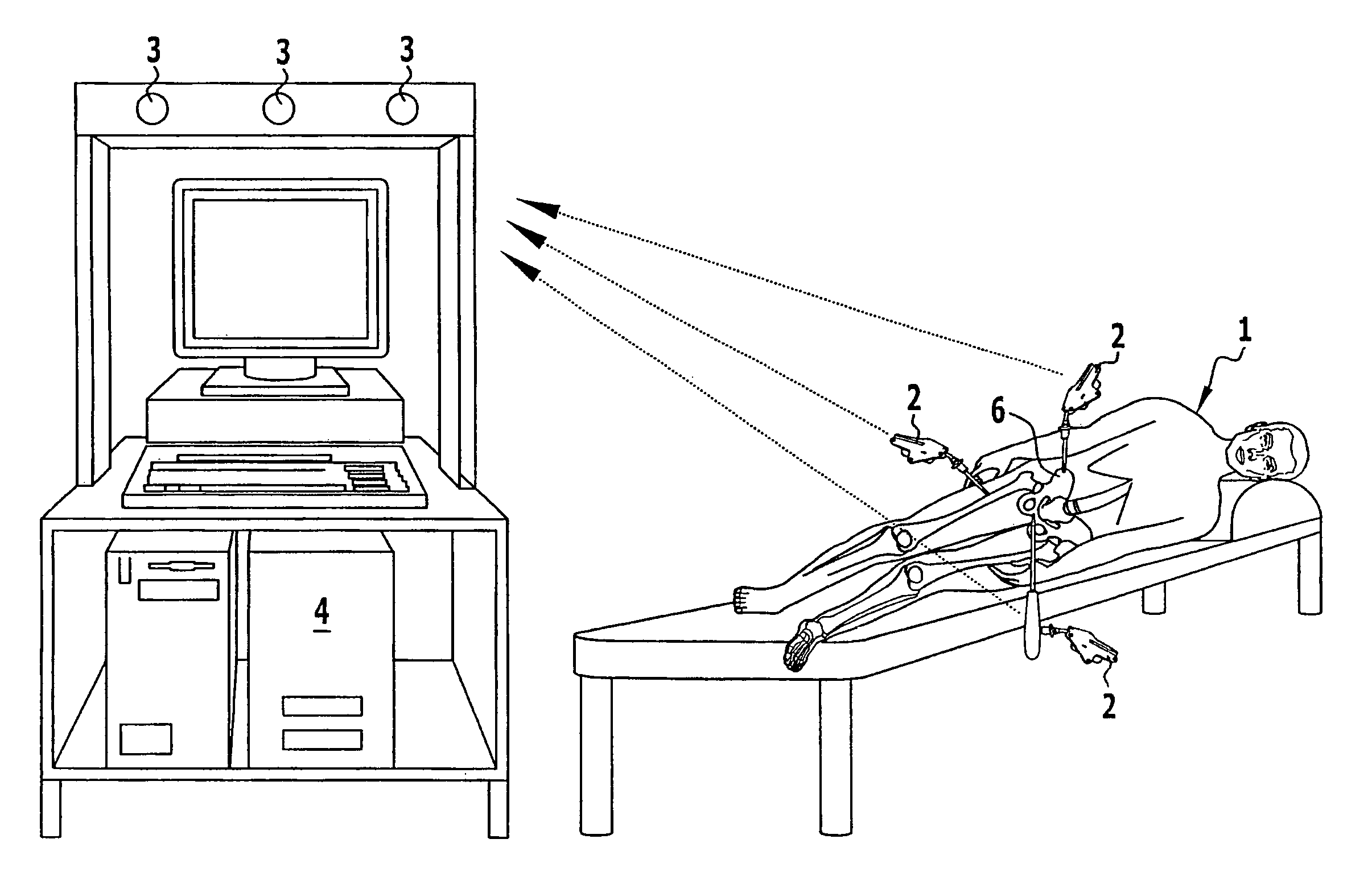
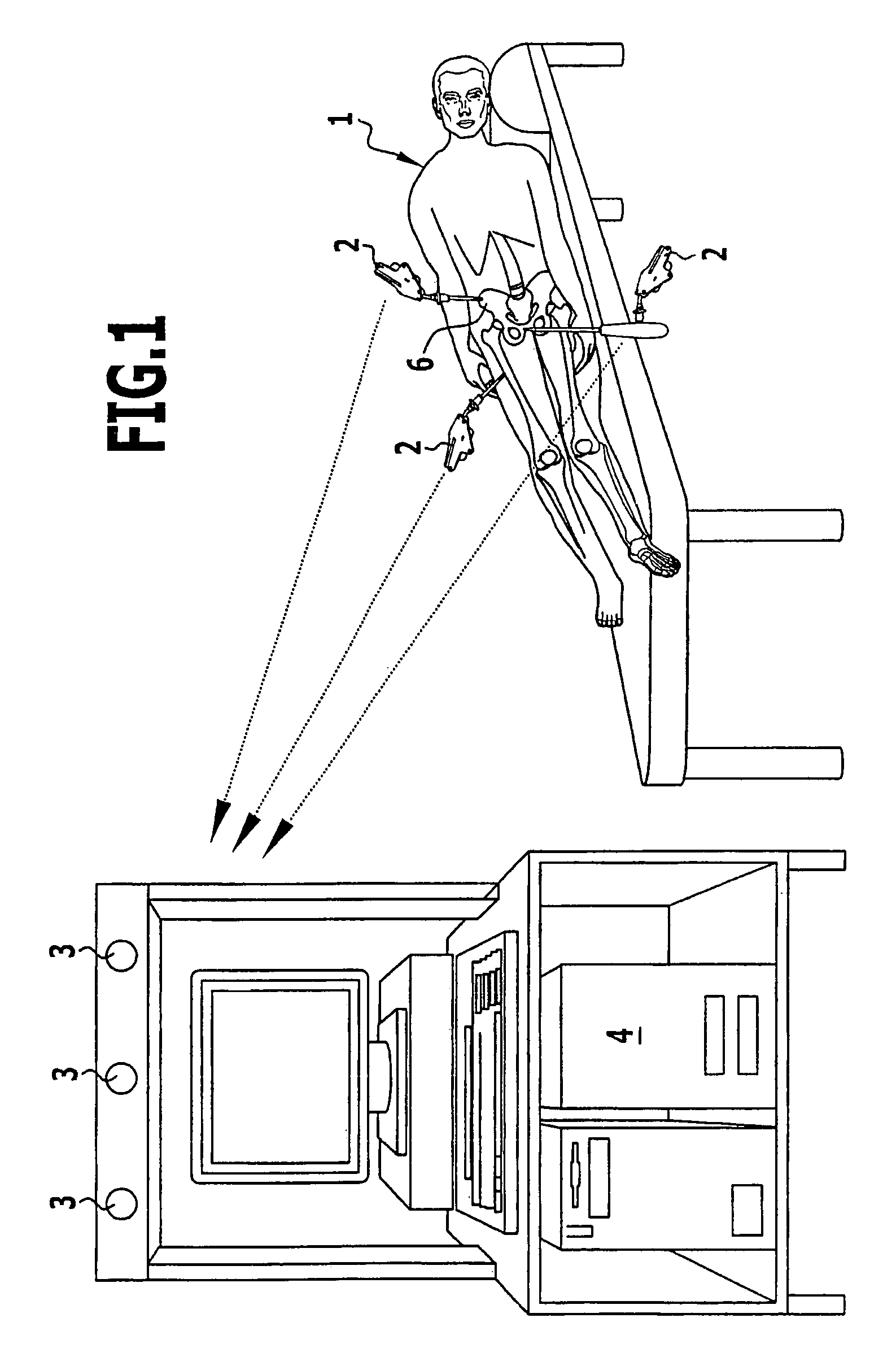
[0060]To perform a hip joint implantation on a patient 1, a navigation system is used that can spatially determine the position and orientation—referred to jointly as disposition—of marking elements 2. These marking elements 2 can be fixedly connected to body parts, instruments etc., and therefore allow the disposition of these body parts and instruments to be spatially determined. In this case, the determination is achieved by means of stationary transmitters 3 that are spaced from one another and at the same time are configured as receivers and receive radiation emitted by them, which is reflected at spaced reflectors of the marking elements 2.

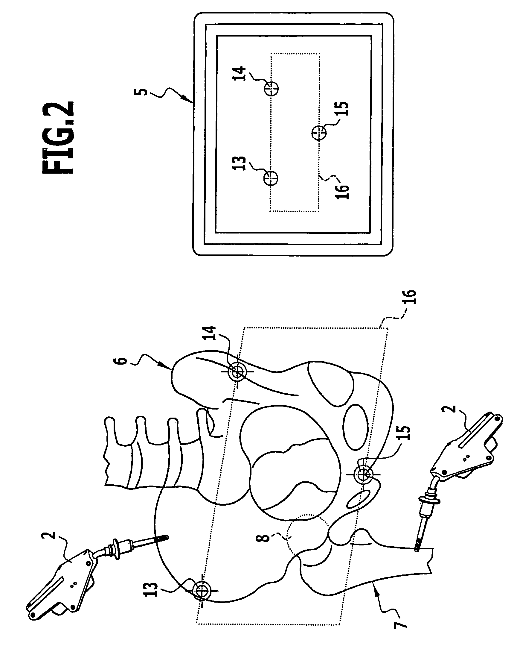
[0061]The position data of the marking elements 2 and thus of the body parts and instruments rigidly connected thereto are recorded in a data processing unit 4 and further processed, and these body parts and instruments can be represented in their disposition relative to one another on a screen 5 controlled by the data processing unit 4.

[006...


PUM


Abstract

A system and method for creating a cavity to receive an acetabulum in a pelvic bone with the aid of a navigated tool are provided. A tear-drop point on a pelvic bone is located by means of a scanning instrument. A tear-drop plane is determined from position data of the tear-drop point and the plane of the pelvic inlet. The tear-drop plane lies perpendicular to the plane of the pelvic inlet, extends parallel to a line connecting the two anterior superior iliac spines, and runs through the tear-drop point. A reference point is determined which is at a defined height above the tear-drop plane, in a defined position in an anterior-posterior direction, and at a defined spacing from an outer surface of the pelvic bone in a lateral-medial direction. A tool is worked into the pelvic bone in a desired direction relative to the reference point.

Description

[0001]This application is a continuation of International patent application no. PCT / EP2006 / 005181 filed on May 31, 2006 and claims the benefit of German patent application no. 10 2005 028 831.6 filed Jun. 15, 2005, each of which is incorporated herein and made a part hereof by reference.BACKGROUND OF THE INVENTION[0002]The invention relates to a method for producing a cavity to receive an acetabulum in a navigated pelvic bone with the aid of a navigated tool.[0003]During implantation of an artificial hip joint, an artificial acetabulum is inserted into the pelvic bone, and for this a cavity that receives the acetabulum must be machined in an anatomically defined orientation into the pelvic bone at the anatomically defined location. These cavities are normally hemispherical and are generated by means of a hemispherical milling cutter. To be able to determine and maintain the precise disposition—i.e. the orientation and position—of the receiving cavity, it is known to navigate the pe...

Claims


Application Information

Patent Timeline
Patent Type & Authority Patents(United States)
IPC IPC(8): A61B5/05A61B19/00
CPCA61B5/064A61B5/103A61B17/1746A61B19/52A61B19/5244A61B5/4504A61B5/4528A61B19/50A61B2019/5255A61B2019/5268A61B5/6878A61B34/10A61B34/20A61B90/36A61B2034/2055A61B2034/2068
Inventor MOLLARD, BENOITLEITNER, FRANCOISKAMMERZELL, SERGEJFRIEDRICH, DIRK
Owner AESCULAP AG
Why Eureka
Try Eureka