
Electrode array for neural stimulation

a neural stimulation and electrode array technology, applied in the field of electrode arrays for neural stimulation, can solve the problems of limited electrode number and device operation lifetime of weeks to months, and achieve the effect of reducing the number of electrical connections

Active Publication Date: 2011-08-16
NAT TECH & ENG SOLUTIONS OF SANDIA LLC
View PDF13 Cites 183 Cited by
  • Summary
  • Abstract
  • Description
  • Claims
  • Application Information

AI Technical Summary

Benefits of technology

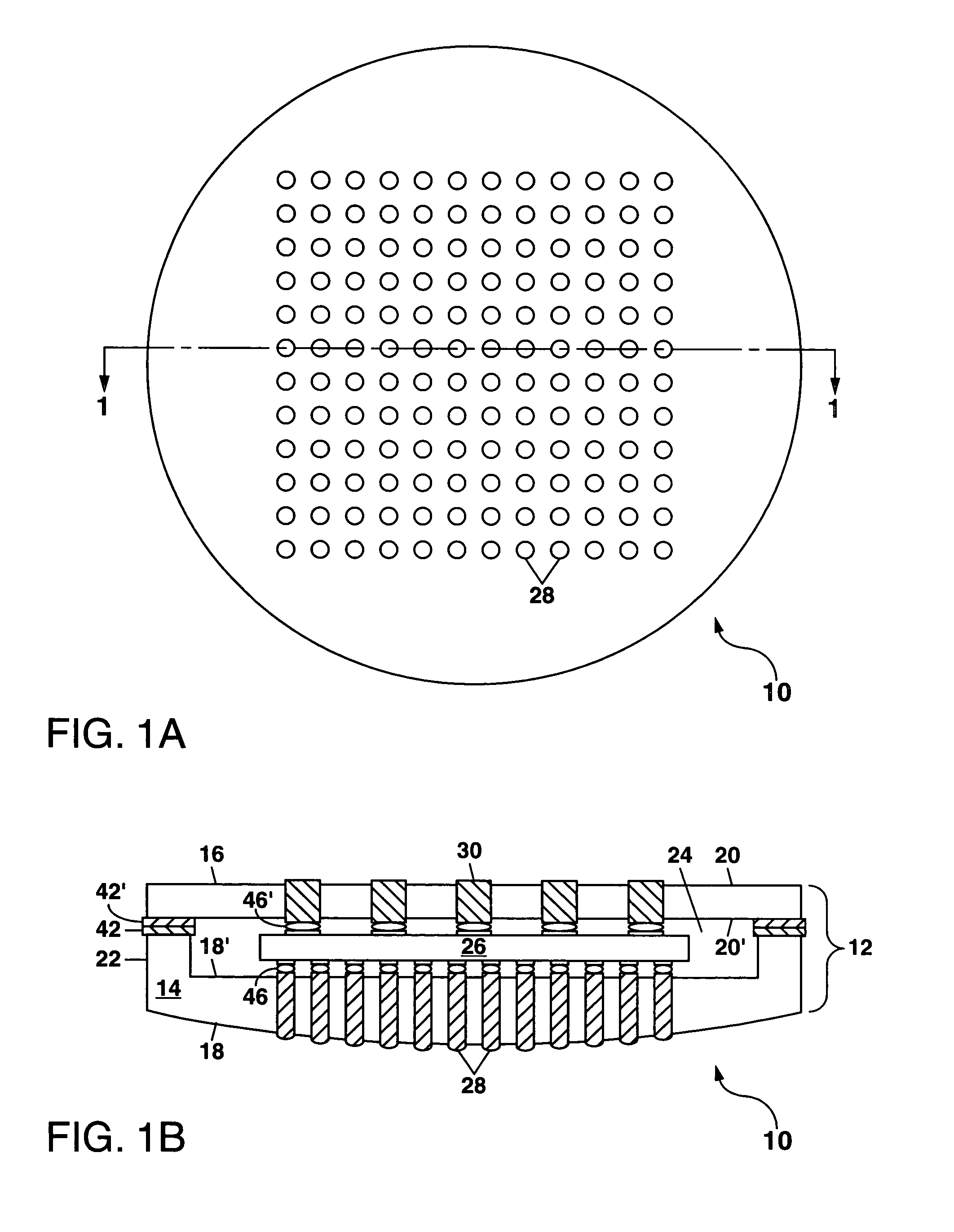
[0008]The present invention relates to an electrode array for neural stimulation which comprises a two-part ceramic package having a ceramic base and a ceramic lid. The ceramic base and the ceramic lid each have a pair of major surfaces, with at least one of the ceramic base and the ceramic lid having a ceramic lip extending outward therefrom to define an interior region between the ceramic base and the ceramic lid. The ceramic lid includes a plurality of electrical connections (also termed vias) extending between the pair of major surfaces thereof; and the ceramic base includes a plurality of electrodes extending between the pair of major surfaces thereof. An electronic circuit is located within the interior region to receive electrical input signals conducted through the plurality of electrical connections and to generate therefrom electrical output signals which are communicated to the plurality of output electrodes for use in neural stimulation. The electrical input signals can be multiplexed to reduce the number of electrical connections to the two-part ceramic package; and the electronic circuit can be a demultiplexer circuit.

Problems solved by technology

Such devices have a limited operational lifetime of weeks to months, and are also limited in the number of electrodes that can be fabricated using this technology.

Method used


Image

  • Electrode array for neural stimulation
  • Electrode array for neural stimulation
  • Electrode array for neural stimulation

Examples


Embodiment Construction

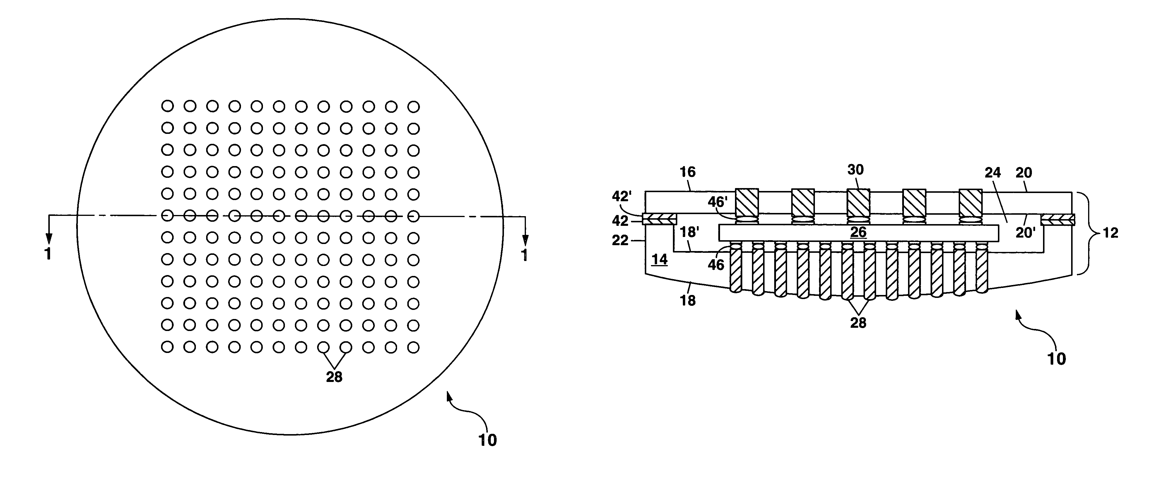
[0028]Referring to FIGS. 1A and 1B, there is shown a schematic plan view and a schematic cross-section view, respectively, of a first example of an electrode array 10 formed according to the present invention. The electrode array 10, which has applications for neural stimulation in a retinal prosthesis, comprises a two-part ceramic package 12 which further comprises a ceramic base 14 and a ceramic lid 16. The ceramic base 14 comprises a pair of major surfaces 18 and 18′; and the ceramic lid 16 comprises another pair of major surfaces 20 and 20′. A ceramic lip 22 extends upward from the ceramic base 14 towards the ceramic lid 20 to form in combination with the major surfaces 18′ and 20′ an interior region 24 wherein an electronic circuit 26 can be located. The electronic circuit 26 is useful to electrically address a plurality of electrodes 28 and to provide electrical output signals to the various electrodes 28 as required for neural stimulation to form an image on a user's retina u...


PUM

PropertyMeasurementUnit
diameteraaaaaaaaaa
diameteraaaaaaaaaa
thicknessaaaaaaaaaa

Abstract

An electrode array for neural stimulation is disclosed which has particular applications for use in a retinal prosthesis. The electrode array can be formed as a hermetically-sealed two-part ceramic package which includes an electronic circuit such as a demultiplexer circuit encapsulated therein. A relatively large number (up to 1000 or more) of individually-addressable electrodes are provided on a curved surface of a ceramic base portion the electrode array, while a much smaller number of electrical connections are provided on a ceramic lid of the electrode array. The base and lid can be attached using a metal-to-metal seal formed by laser brazing. Electrical connections to the electrode array can be provided by a flexible ribbon cable which can also be used to secure the electrode array in place.

Description

GOVERNMENT RIGHTS[0001]This invention was made with Government support under Contract No. DE-AC04-94AL85000 awarded by the U.S. Department of Energy. The Government has certain rights in the invention.FIELD OF THE INVENTION[0002]The present invention relates in general to electrode arrays for neural stimulation, and in particular to a ceramic electrode array package which can be hermetically sealed for use in prosthetic devices including an implantable retinal prosthesis.BACKGROUND OF THE INVENTION[0003]Efforts are currently underway in a number of groups worldwide to develop an implantable retinal prosthesis to restore at least partial sight to persons suffering from certain forms of blindness due to end-stage photoreceptor degenerative diseases such as age-related macular degeneration and hereditary retinitis pigmentosa. See J. D. Weiland et al., “A Biomimetic Retinal Stimulating Array,”IEEE Engineering in Medicine and Biology Magazine, pp. 14-21, September / October 2005 for a rece...

Claims


Application Information

Patent Timeline
Patent Type & Authority Patents(United States)
IPC IPC(8): A61N1/00
CPCA61N1/0543A61N1/36046
Inventor WESSENDORF, KURT O.OKANDAN, MURATSTEIN, DAVID J.YANG, PINCESARANO, III, JOSEPHDELLINGER, JENNIFER
Owner NAT TECH & ENG SOLUTIONS OF SANDIA LLC
Learn More