Spinal stabilization device and methods

a technology of spinal stabilization device and spinal column, applied in the field of spinal stabilization device and method, can solve the problems of pain or limited physical activity and ability of people, lack of mobility, further damage and degeneration of spinal health,

Active Publication Date: 2011-08-23
XTANT MEDICAL HLDG INC
View PDF46 Cites 64 Cited by
  • Summary
  • Abstract
  • Description
  • Claims
  • Application Information

AI Technical Summary

Benefits of technology

[0018]According to another aspect of the invention, an implant device is provided for implantation within an intervertebral space between adjacent vertebrae, which comprises an implant body having opposite end portions and a longitudinal axis extending between the end portions, opposite side slots in the body for turning the body in a predetermined rotary direction about the longitudinal axis to implant the body between the vertebrae, upper and lower surfaces including gripping structure for securing the implant body between adjacent vertebrae upon turning of the implant body in the predetermined rotary direction in the intervertebral space, and diagonally-opposed corner portions, the corner portions having an arcuate configuration and being arranged on the implant body so that with the implant body inserted between the adjacent vertebrae, turning the implant body in the predetermined rotary direction shifts the arcuate corner portions generally laterally inward in the intervertebral space with the arcuate configuration of the corner portions minimizing damage to the adjacent vertebrae during the turning of the implant body.
[0019]According to yet another aspect of the invention, an implant device is provided for implantation within an intervertebral space between adjacent vertebrae, which comprises an implant body having insertion and trailing end portions, an intermediate concave surface portion of the implant body, a first recessed engagement portion at the trailing end portion, and a second recessed engagement portion at the insertion end portion, the first and second recessed engagement portions oriented to receive a portion of an insertion tool therein and the concave surface portion and the first and second recessed portions cooperating to provide a large size space for receipt of graft material.

Problems solved by technology

A variety of spinal conditions result in a person experiencing pain or limited physical activity and ability.
Some of these conditions can be life-threatening, while others cause impingement on the spinal cord resulting in pain and a lack of mobility.
However, the absence of proper medical care may lead to further damage and degeneration of spinal health and to permanent spinal cord damage.
Damage to the spine often results in a reduced physiological capability.
In more severe cases, the damage may allow the nucleus to leak from the annulus.
These same results may be brought about by a damaged or fractured vertebra.
In any event, such damage often causes the vertebrae to shift closer or compress, and often causes a portion of the disc to press against the spinal cord.
This prescription sacrifices the rotation or flexion between the affected vertebrae, such that some loss of movement and flexibility is experienced.
Once excavated, the adjacent vertebrae have a tendency to shift toward each other a small amount, thereby compressing the space or volume.
However, if the vertebrae are not sufficiently distracted, VBR insertion can be difficult due to resistance generated when the teeth engage the vertebrae, particularly if the implant needs to be redirected or turned in the intervertebral space to an implantation orientation that is offset from the insertion orientation thereof.
Accordingly, rotation of the VBR in the intervertebral space may result in significant stress upon the VBR since the rotation may require forcing the vertebrae apart a small amount.
Because the VBR typically has a body of relatively small size for fitting in the intervertebral space and particularly if cavities are formed therein for graft material, VBR rotation can generate undesirably high compressive force on the VBR.
However, this solution comes at the expense of having the VBR securely positioned in the intervertebral space with the teeth securely gripping the adjacent vertebral surfaces.
Unfortunately, these stronger materials are not bio-resorbable.
This results in a boundary interface between the implant device and any resultant bone growth.
However, as mentioned, this is done at the cost of having secure implantation of the VBR.
However, as these bone chips are loose and oftentimes fragile, migration of the bone chips from the intervertebral space presents an issue.
Another issue confronted with the implantation of the VBR is in situ adjustments or positioning.
Once rotated, the teeth are engaged with the endplates thereby making adjustment difficult.
If extensive adjustments are made in situ, the teeth may erode or carve out additional space which reduces the distance between the vertebrae.
Often such impingement is difficult to recognize until after the fusion has progressed to a point where revision surgery is difficult and complicated.

Method used


Image

  • Spinal stabilization device and methods
  • Spinal stabilization device and methods
  • Spinal stabilization device and methods

Examples


Embodiment Construction

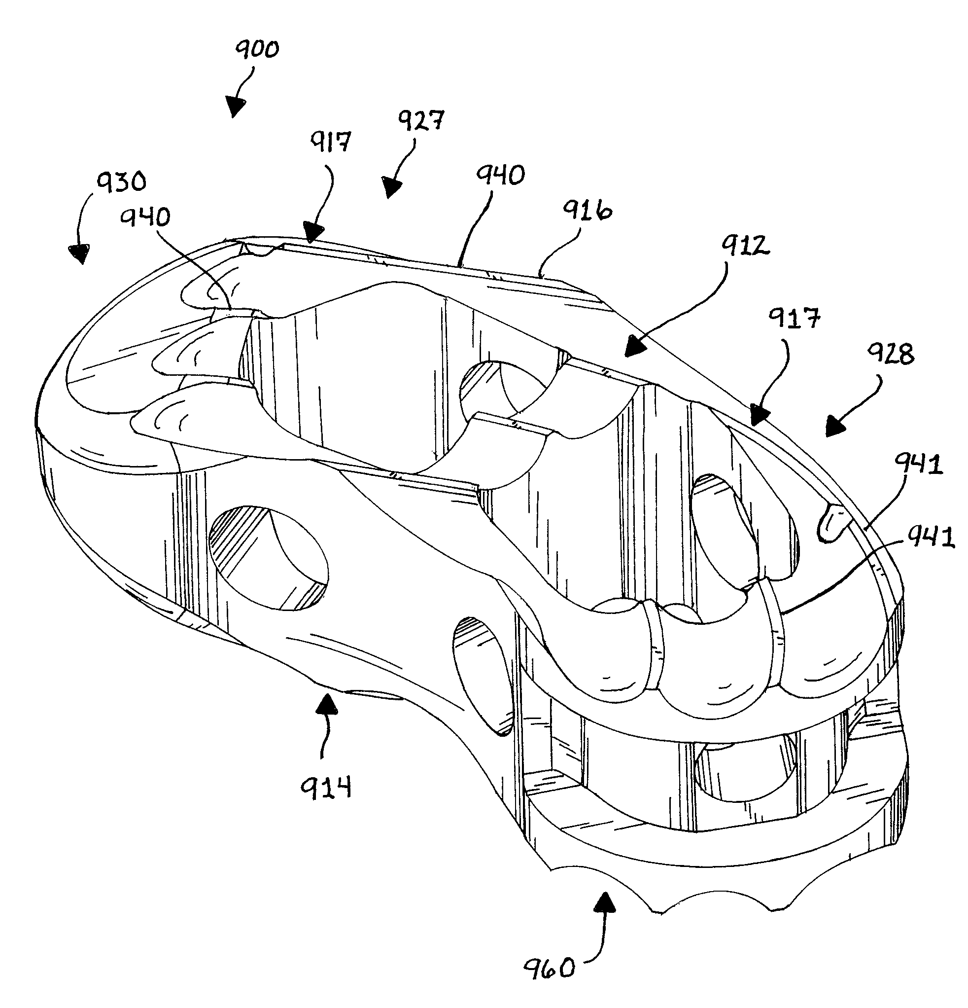
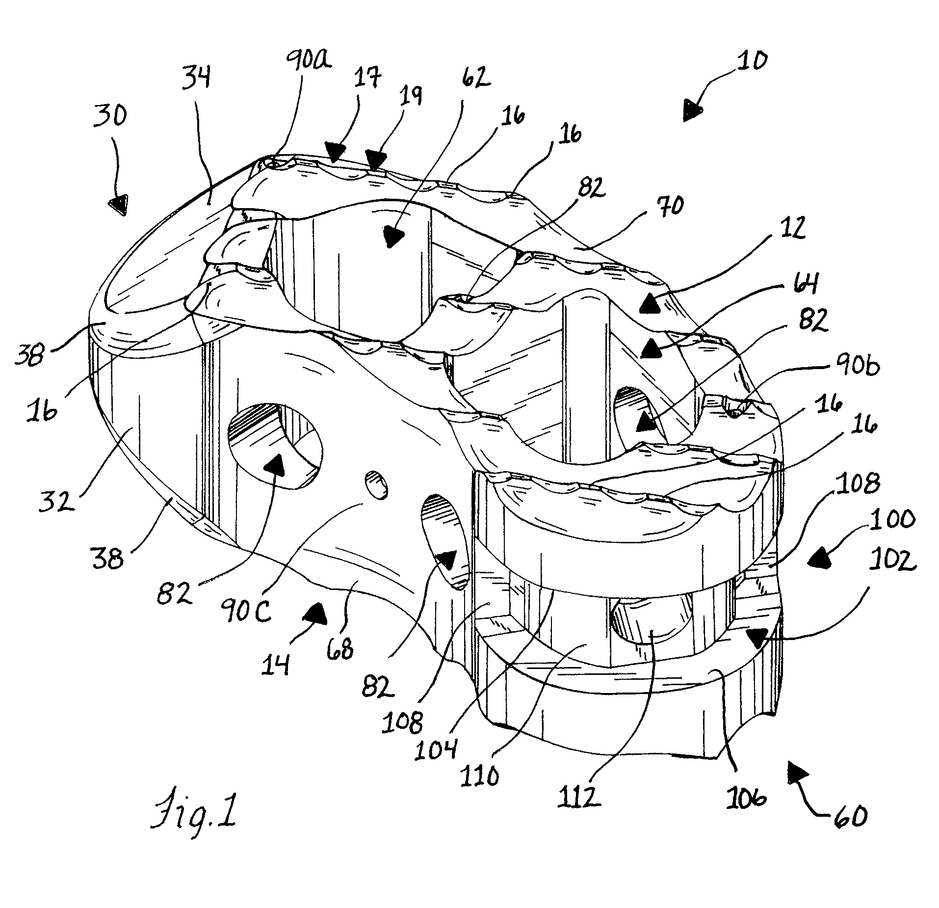
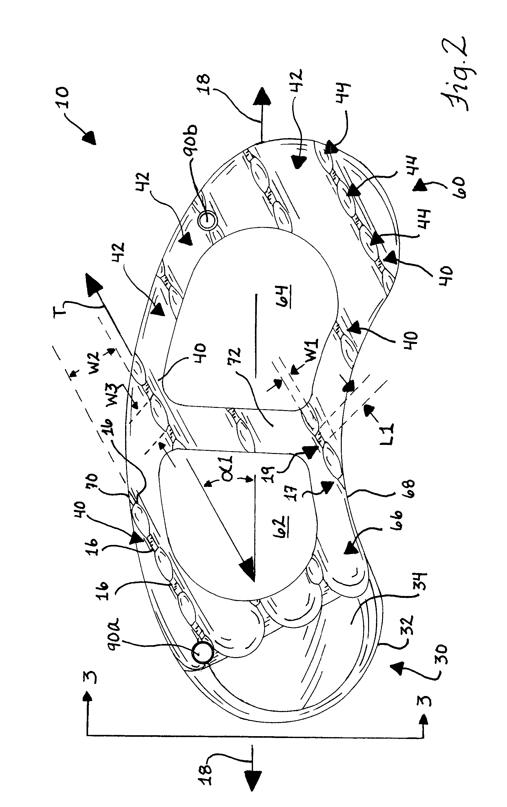
[0089]Referring initially to FIG. 1, an implant device in the form of a vertebral body replacement device (VBR) 10 for spinal fusion surgery is illustrated for implantation within an intervertebral space between adjacent vertebrae. The VBR 10 enables the fusion surgery to be completed with a single VBR 10. As best seen in FIG. 2, the VBR 10 has a generally concavo-convex configuration along a longitudinal axis 18 of the VBR. As illustrated in FIG. 58, once implanted, the longitudinal axis 18 of the VBR extends generally laterally, that is, perpendicular to the anterior-posterior axis of the spine. Accordingly, the VBR 10 is curved so as to have a shape similar to that of a natural spinal disc. Thus, the VBR 10 is able to provide support to the spinal column across a large area.

[0090]The VBR 10 includes a number of features for promoting insertion within the intervertebral space, one of which is the shape of an insertion end 30 formed on an end of a body portion 26. During implantati...


PUM


Abstract

Implant devices in the form of a vertebral body replacement for implantation within an intervertebral space between adjacent vertebrae is disclosed for immobilization and support of the adjacent vertebrae in a desired spatial relationship and for promotion of fusion by the adjacent vertebrae. Instruments for insertion and implantation of the implant devices and of fusion material such as bone graft material are disclosed. Methods are disclosed for implantation of the implant devices.

Description

CROSS REFERENCE TO RELATED APPLICATIONS[0001]This application claims the benefit of the filing date of U.S. Provisional Application 60 / 802,038 which is hereby incorporated in its entirety herein.FIELD OF THE INVENTION[0002]The invention relates to spinal stabilization devices and methods and, in particular, to devices for implantation in an intervertebral disc space for immobilization and fusion of adjacent vertebrae, to methods for the implantation of such devices, and to instruments for performing the implantation.BACKGROUND OF THE INVENTION[0003]A variety of spinal conditions result in a person experiencing pain or limited physical activity and ability. More specifically, damage to vertebrae composing the spine and spinal discs between the vertebrae may occur as a result of trauma, deformity, disease, or other degenerative conditions. Some of these conditions can be life-threatening, while others cause impingement on the spinal cord resulting in pain and a lack of mobility. Remov...

Claims


Application Information

Patent Timeline
Patent Type & Authority Patents(United States)
IPC IPC(8): A61F2/44
CPCA61B17/92A61F2/30771A61F2/4455A61F2/4465A61F2/4611A61F2/4684A61B2017/922A61F2002/2835A61F2002/3008A61F2002/30112A61F2002/30153A61F2002/30166A61F2002/30601A61F2002/30616A61F2002/30772A61F2002/3082A61F2002/30825A61F2002/30879A61F2002/30904A61F2002/448A61F2002/4627A61F2002/4629A61F2002/4681A61F2230/0004A61F2230/0019A61F2230/0028A61F2250/0098
Inventor STREAM, KATIEPALTZER, ADAMPERNSTEINER, WESTONJANOWSKI, BRIAN P.MORELAND, DOUGLAS B.CORIC, DOMAGOJ
Owner XTANT MEDICAL HLDG INC
Why Eureka
Try Eureka