Drive apparatus for a vacuum fluorescent display

a technology of vacuum fluorescent display and drive circuit, which is applied in the direction of electric variable regulation, process and machine control, instruments, etc., can solve the problems of inconvenient separate supply of power to filament and other electrical loads, waste of power dissipation in the voltage dropper device, etc., and achieve the effect of reducing the power dissipation of the shunt voltage regulator and avoiding the cost of providing additional voltage regulators for other electrical loads

Active Publication Date: 2011-08-23
APTIV TECH LTD
View PDF5 Cites 2 Cited by
  • Summary
  • Abstract
  • Description
  • Claims
  • Application Information

AI Technical Summary

Benefits of technology

[0005]The present invention is directed to an improved drive apparatus for a VFD, where the filament of the display is coupled at a first end to an input voltage derived from a voltage source, and at a second end to a shunt voltage regulator that establishes a regulated filament current and a regulated cutoff voltage with respect to ground potential. Other electrical loads such as drive circuitry for the anodes and grid of the display are coupled between the second end of the filament and ground potential so that at least a portion of the filament current is supplied to such other electrical loads. Power dissipated by the shunt voltage regulator is thereby reduced, and the cost associated with providing additional voltage regulators for the other electrical loads is avoided.

Problems solved by technology

The main problem with the above-described arrangement is that the power dissipated in the voltage-dropping device is essentially wasted.
Additionally, separately supplying power to the filament and the other electrical loads is not particularly cost-effective.

Method used


Image

  • Drive apparatus for a vacuum fluorescent display
  • Drive apparatus for a vacuum fluorescent display

Examples


Embodiment Construction

[0008]The drive apparatus of the present invention is disclosed herein in the context of an instrument panel display powered from the storage battery of a motor vehicle, but it should be understood that the disclosed drive apparatus is equally applicable to other vehicular and non-vehicular applications.

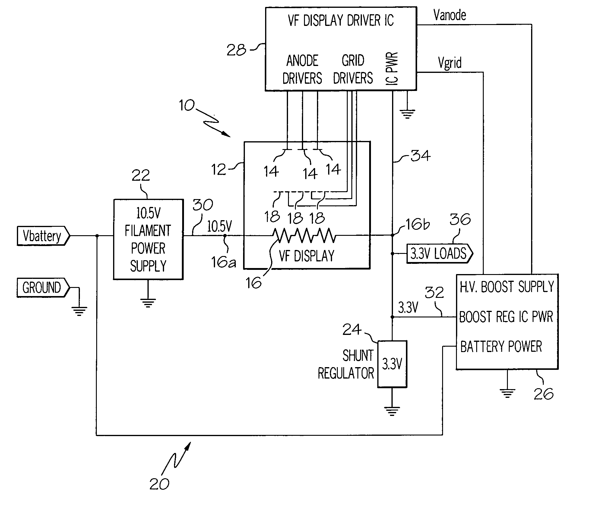
[0009]Referring to FIG. 1, the reference numeral 10 generally designates a conventional VFD including an evacuated glass housing 12, a number of phosphored anode segments 14, a filament or cathode 16, and a number of grid segments 18 disposed between the filament 16 and the anode segments 14. In general, the display 10 is activated by passing electrical current through the filament 16 to generate a localized cloud of electrons, and supplying positive voltages to selected anode and grid segments 14, 18 to drive the electrons into the selected anode segments. To prevent anode illumination, the respective grid segments 18 are held at a voltage potential that is negative with respect to ...


PUM


Abstract

A VFD drive apparatus in which the filament of a VFD is coupled at a first terminal to an input voltage derived from a voltage source, and at a second terminal to a shunt voltage regulator that establishes a regulated filament current and a regulated cutoff voltage with respect to ground potential. Other electrical loads such as drive circuitry for the anodes and grid of the display are coupled between the second terminal of the filament and ground potential so that at least a portion of the filament current is supplied to such other electrical loads. Power dissipated by the shunt voltage regulator is thereby reduced, and the cost associated with providing additional voltage regulators for the other electrical loads is avoided.

Description

TECHNICAL FIELD[0001]The present invention relates to an efficient and low-cost drive circuit for a vacuum fluorescent display (VFD).BACKGROUND OF THE INVENTION[0002]Vacuum fluorescent displays (VFDs) are typically manufactured in the form of a glass housing having an evacuated central cavity containing phosphored anode segments arranged in a suitable display pattern, a filament (cathode), and a grid disposed between the filament and the anode segments. The filament is electrically heated to generate a cloud of electrons, and selected anode segments are illuminated when positive voltages are supplied to the grid and the selected anode segments. And to turn off the display, the grid is held at a negative potential with respect to the filament.[0003]In applications where a single DC voltage source is used to drive a VFD, one end of the filament can be coupled to the source voltage, with the other end of the filament being coupled to ground potential (i.e., the negative terminal of the...

Claims


Application Information

Patent Timeline
Patent Type & Authority Patents(United States)
IPC IPC(8): H05B37/00
CPCH05B41/14H02M2001/0006H02M1/0006
Inventor MADSEN, WAYNE A.BETTS, ANDREW R.
Owner APTIV TECH LTD
Why Eureka
Try Eureka