Photometric instrument

a technology of photometric instruments and spot images, applied in instruments, spectrometry/spectrophotometry/monochromators, optical radiation measurement, etc., can solve the problems of unable to identify the species of phosphors, affecting the accuracy of spot images, etc., to achieve the effect of high accuracy

Inactive Publication Date: 2011-08-23
HITACHI HIGH-TECH CORP
View PDF9 Cites 0 Cited by
  • Summary
  • Abstract
  • Description
  • Claims
  • Application Information

AI Technical Summary

Benefits of technology

[0008]In an instrument for analyzing biomolecules through imaging of fluorescence of the biomolecules fixed on a surface of a substrate, generally, different kinds of biomolecules are respectively fixed on different spots on the substrate, and fluorescence from the respective spots is separated and then detected through the imaging. In order to analyze many kinds of biomolecules in minimal time, and to reduce a consumption of reagents, it is favorable to form spots so that the biomolecules can be fixed on the substrate as densely as possible to the extent allowing optical resolution thereof. Additionally, so as to reduce a consumption of reagents per spot, it is more advantageous to fix a smaller number of biomolecules in one spot, and the number is ideally one. As described in Funatsu et al., Nature Vol. 374, 555-559 (1995), although a fluorescence detection method has a sufficient sensitivity for detecting even one molecule, a spectral imaging method causing only a smaller loss is preferable for the purpose of obtaining a favorable S / N ratio in spectroscopically detecting fluorescence from a small number of molecules. For this reason, preferable methods for this purpose are a dispersive spectral imaging method using a dispersing element such as a prism or a diffraction grating, and a method (dichroic / multi-sensor spectral imaging method) in which multiple image sensors respectively acquires images from light spectrally separated by a dichroic mirror.
[0012]The present invention was made in consideration of the above described situations, and is configured to provide photometrical analysis based on a spectral imaging method capable of highly-accurately associating spot images with spots on a specimen (identifying correspondences therebetween) and also highly-accurately determining a phosphor species having become luminous.
[0020]According to the photometrical analyze based on the spectral imaging method of the present invention, it is possible to associate spot images with spots on a specimen (identifying correspondences therebetween) and to judge a phosphors species having become luminous with high accuracy.

Problems solved by technology

The dispersive spectral imaging method, however, has the following problem because a change in wavelength of fluorescence is converted into a change in spot image positions in a fluorescence image.
In this case, the dispersive spectral imaging method cannot determine which spot the fluorescence has been emitted from, based on spot positions in the fluorescence image, and thus fails to identify the species of the phosphors having emitted the fluorescence.
In reality, however, images of fluorescence from the same spot are inevitably positioned slightly differently from one sensor to another because of such reasons as differences in imaging magnification, incompletion of optical adjustments, chromatic aberrations, and individual differences among the sensors.
Additionally, because an S / N ratio of fluorescence detection from a small number of molecules is not necessarily sufficiently high, a center position of a spot image may vary over time.
In addition, when the spots are implemented at the maximum density allowed by its optical resolution, the dichroic / multi-sensor spectral imaging method may also cause an error in judgment on which spot on the substrate a spot image originates from.
As described above, in the highly sensitive spectral imaging methods, it has been difficult to highly-accurately associate, as a pair, a spot in a fluorescence image with a spot on a specimen substrate.

Method used


Image

  • Photometric instrument
  • Photometric instrument
  • Photometric instrument

Examples


first embodiment

1. Constitution of Photometric Instrument

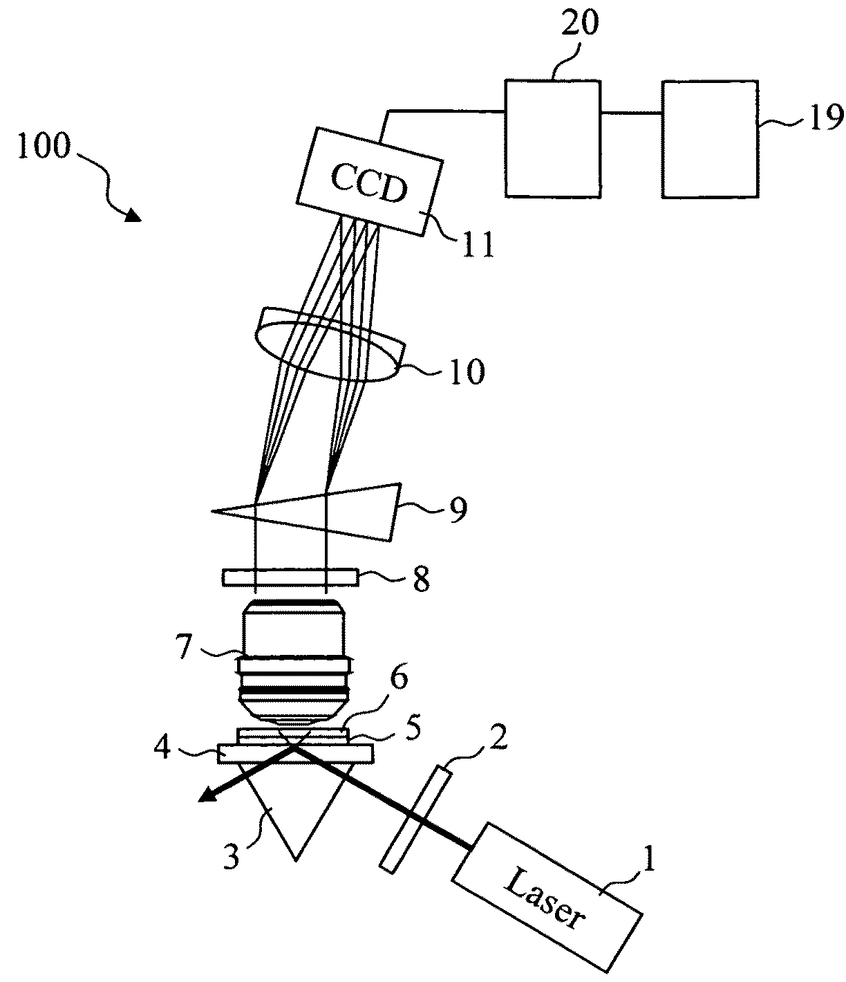
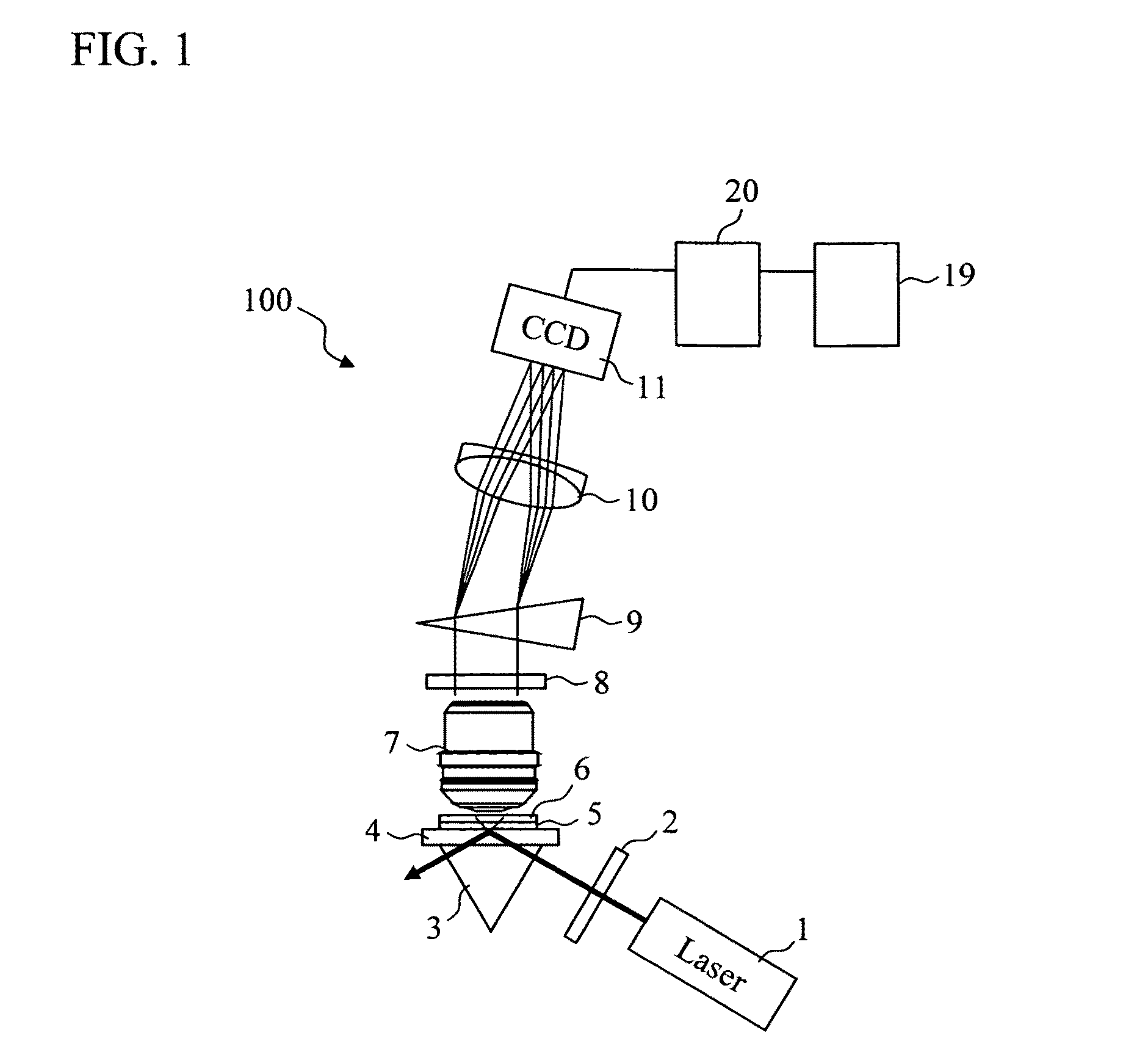
[0038]FIG. 1 is a view showing a schematic constitution of a photometric instrument 100 according to a first embodiment of the present invention. In FIG. 1, after spectral purity thereof is enhanced by an excitation filter 2, excitation light emitted from an excitation source 1 enters a prism 3 and then enters a substrate 4. A space between the prism 3 and the substrate 4 is filled with matching oil, whereby total reflection is prevented from occurring on interfaces of these. The excitation light having entered the substrate 4 is totally reflected by an upper surface thereof, and generates evanescent waves on a surface of the substrate. A space between the upper surface of the substrate 4 and a cover glass 6 is filled with a reaction solution 5.

[0039]Luminescence from the surface of the substrate, which is excited by the evanescent waves, is condensed and collimated by an objective lens 7, and thereafter, a component (elastic scattered light)...

second embodiment

[0059]The same constitution as that of the photometric instrument 100 according to the first embodiment can be applied to a photometric instrument according to a second embodiment. Therefore, description regarding the constitution of the instrument will be omitted. Additionally, the same processing as that in the first embodiment can be applied to base species judgment here as well.

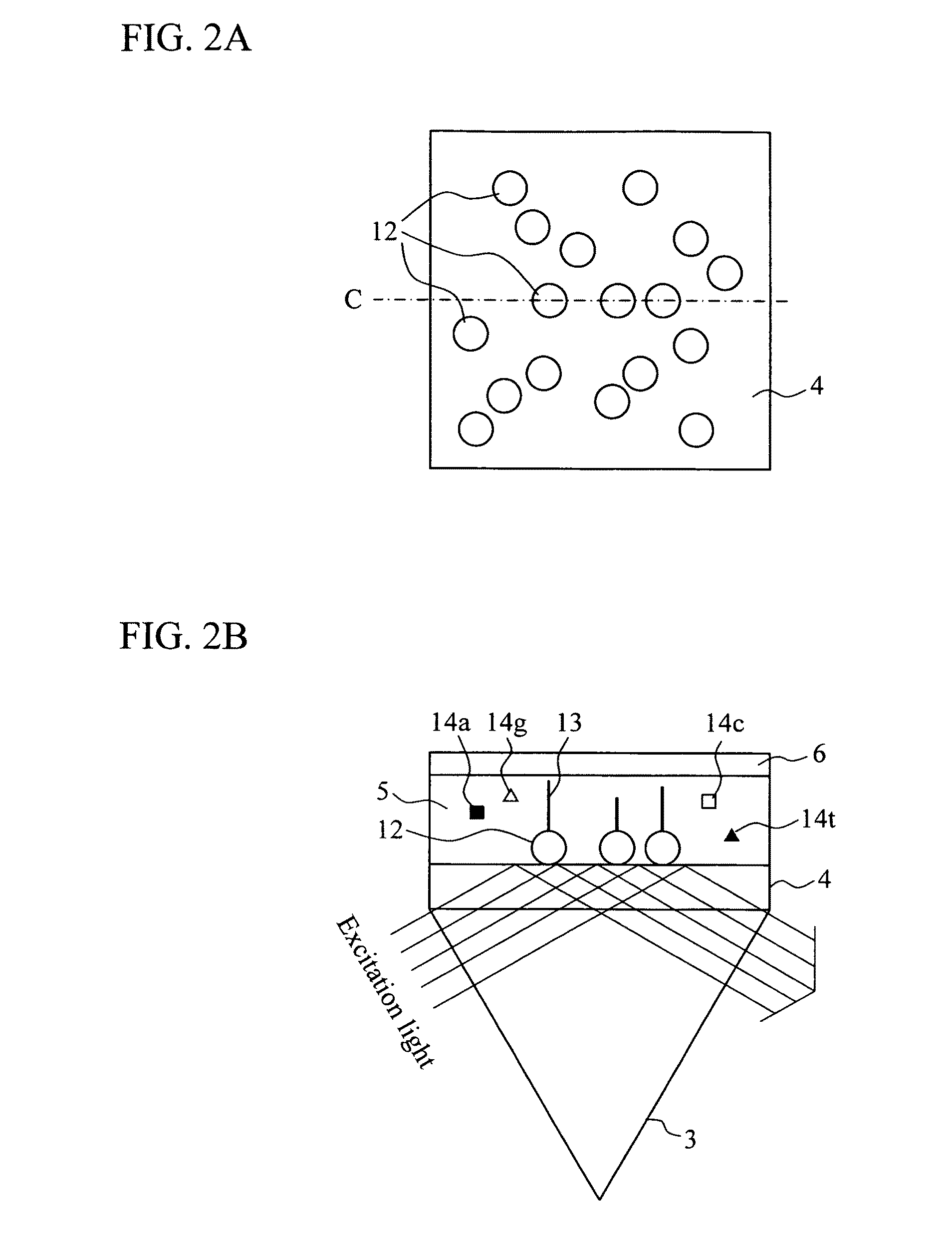
[0060]FIGS. 6A and 6B are enlarged views of the vicinity of the substrate 4 in the second embodiment. FIG. 6A is a top view of the substrate, and FIG. 6B is a cross-sectional view taken along an alternate long and short dash line C in FIG. 6A.

[0061]In this embodiment, the structures on which biomolecules are fixed are arranged in a lattice pattern by use of a semiconductor process. Furthermore, although EB (electron beam) drawing is used in the manufacturing process here, any one of dry etching and wet etching may be used.

[0062]By thus configuring the constitution, the structures (for example, gold partic...

third embodiment

[0063]The same constitution as that of the photometric instrument 100 according to the first embodiment can be applied to a photometric instrument according to a third embodiment. Therefore, description regarding the constitution of the instrument will be omitted. Additionally, the same processing as that in the first embodiment can be applied to base species judgment here as well.

[0064]FIGS. 7A and 7B are enlarged views of the vicinity of the substrate 4 in the third embodiment. FIG. 7A is a top view of the substrate, and FIG. 7B is a cross-sectional view taken along an alternate long and short dash line C in FIG. 7A.

[0065]In this embodiment, minute apertures provided to a metallic thin film are used as the structures on which biomolecules are fixed. Apertures each having a diameter of 100 nm are provided on an aluminum thin film through EB drawing with 2.3 micron pitches in lateral directions and with 1 micron pitches in longitudinal directions. However, a thin film made of any me...


PUM


Abstract

A metallic structure is provided on a surface of a substrate. A component having a longer wavelength than excitation light is detected from luminescence from fixation positions of biomolecules and emitted from a material other than the biomolecules, and is used for photometrical analysis. As the structure, usable is a particulate (a metallic structure of a size not larger than a wavelength of the excitation light), a minute protrusion, or a thin film with minute apertures, which are made of a metal such as gold, chrome, silver or aluminum. In the case of the particulate or the minute protrusion, photoluminescence of the structure is detected with a biomolecule being fixed thereon. In the case of the thin film with minute apertures, Raman scattered light of specimen solution around the biomolecules, and photoluminescence of the metallic structure near the biomolecules are detected with biomolecules being fixed in the apertures.

Description

CLAIM OF PRIORITY[0001]The present application claims priority from Japanese patent application JP 2007-301274 filed on Nov. 21, 2007 and JP 2008-219804 filed on Aug. 28, 2008, the content of which is hereby incorporated by reference into this application.BACKGROUND OF THE INVENTION[0002]1. Field of the Invention[0003]The present invention relates to a photometric instrument. For example, it relates to a photometric instrument which photometrically analyzes biopolymer by irradiating the biopolymer with light.[0004]2. Description of the Related Art[0005]Conventionally, there have been proposed methods of observing a configuration of an object, which is placed on a surface of a substrate, by irradiating the object with excitation light. In Japanese Patent Application Publication No. Hei 9-257813 (hereinafter, JP-A 9-257813), for example, there is described an instrument which irradiates a transparent substrate with excitation light emitted from an excitation source, generates evanesce...

Claims


Application Information

Patent Timeline
Patent Type & Authority Patents(United States)
IPC IPC(8): G01J3/30
CPCG01N21/6456G01N21/648G01N2021/6423
Inventor SONEHARA, TSUYOSHITAKAHASHI, SATOSHISAKAI, TOMOYUKI
Owner HITACHI HIGH-TECH CORP
Why Eureka
Try Eureka