Optical interferometer and method

an interferometer and optical technology, applied in the field of optical interferometers, can solve the problems of insufficient separation, complex setup, and large volume of the tunable interferometer, and achieve the effect of less component coun

Inactive Publication Date: 2011-08-23
LI CHIAN CHIU
View PDF13 Cites 19 Cited by
  • Summary
  • Abstract
  • Description
  • Claims
  • Application Information

AI Technical Summary

Problems solved by technology

But a tunable interferometer is often complex and bulky.
This setup, however, is hardly compact.
But the detector array has to be placed at a distance far enough from the grating; otherwise, neighboring sub-beams may not separate adequately, which affects resolving resolution.

Method used


Image

  • Optical interferometer and method
  • Optical interferometer and method
  • Optical interferometer and method

Examples


Embodiment Construction

FIGS. 1-A to 1-D—Prior-Art

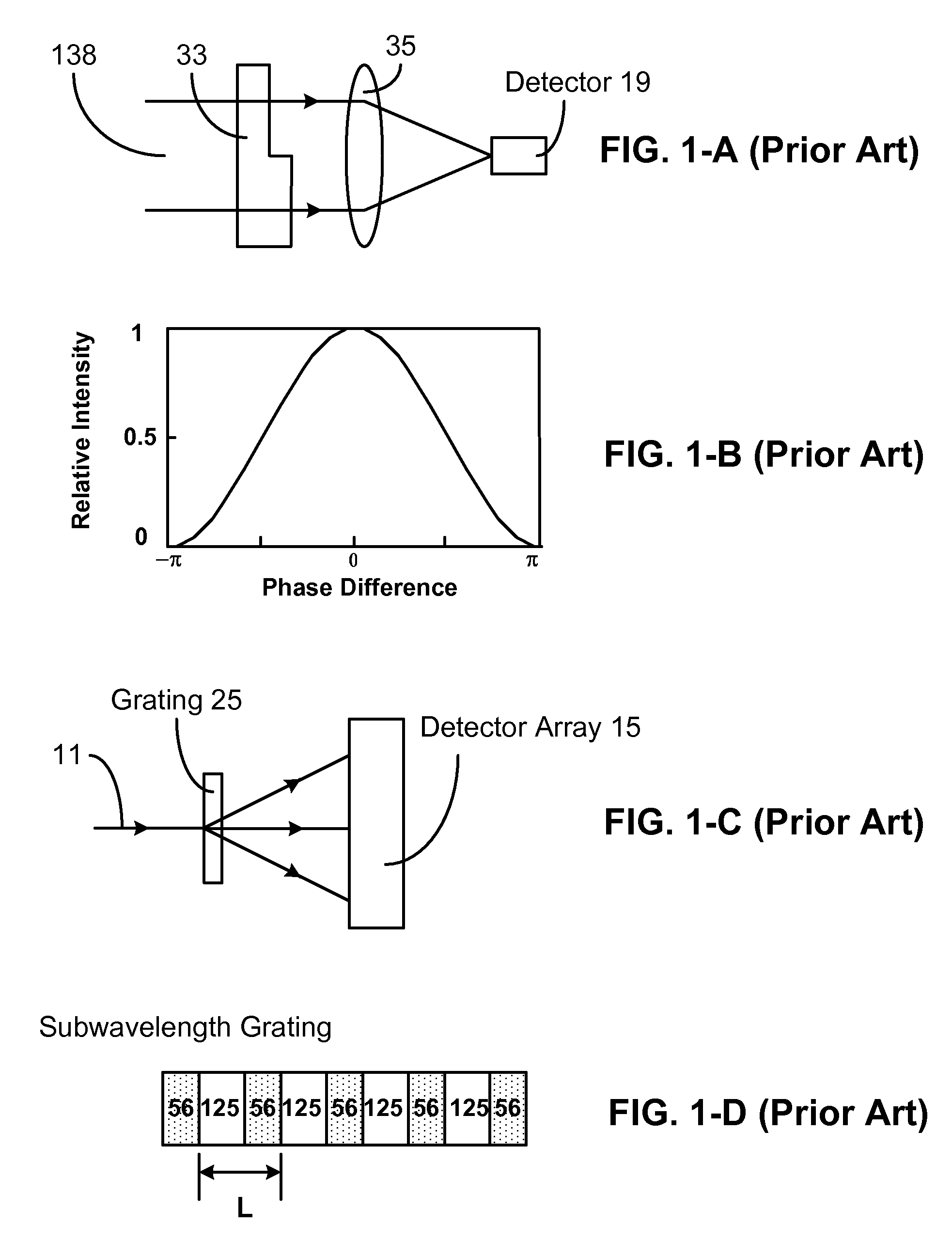
[0036]FIG. 1-A is a schematic diagram of a prior-art interferometer. A beam 138 is transmitted through a spatial phase modulator 104 and then focused onto a detector 19 by a lens system 106. Modulator 104 divides beam 138 by wavefront division. The beam is split into two beam portions having different phase retardation. Detector 19 measures interference intensity by the beam portions. FIG. 1-B shows a curve of interference intensity versus phase difference. Because phase of a beam is related to its wavelength, the curve indicates the setup may be used as a band pass filter which lets pass of light having a wavelength while blocking light of other wavelengths. Since one interferometer works for selecting one wavelength, a group of interferometers can be used as a spectrometer.

[0037]FIG. 1-C shows a prior-art spectrometer using diffraction grating. A diffraction grating contains materials which form a periodic optical structure. In FIG. 1-C, a beam 11 is tran...


PUM


Abstract

Disclosed are compact optical interferometer array, miniature optical interferometer array, and miniature optical interferometer. The interferometer arrays contain a spatial phase modulator array and a detector array. They are used for conducting multiple measurements. The miniature interferometer has only one component—a spatial phase modulator. Without passing through any focus lens, beam portions coming out of the modulator spread and merge together by themselves. Size of the miniature interferometer can reach subwavelength or even nanoscale. The interferometer array and miniature interferometer find applications in miniature spectrometer, color filter, display, adjustable subwavelength grating, etc.

Description

CROSS REFERENCE TO RELATED APPLICATION[0001]This application is entitled to the benefit of Provisional Patent Application Ser. No. 60 / 806,286, filed Jun. 30, 2006.FEDERALLY SPONSORED RESEARCH[0002]Not applicableSEQUENCE LISTING OR PROGRAM[0003]Not applicableBACKGROUND[0004]1. Field of Invention[0005]This invention relates to optical interferometer, and particularly to optical interferometer array and miniature optical interferometer.[0006]2. Description of Prior Art[0007]Optical interferometer is an indispensable measurement tool in many fields. It is desirable for an interferometer to make different measurements. It is also desirable to have a small-size interferometer, which is useful for integration with other systems.[0008]Usually, optical interference is created by splitting a beam into two parts either through amplitude division or wavefront division and then recombining the two parts. Amplitude-division may be realized by a beamsplitter and wavefront-division by a spatial pha...

Claims


Application Information

Patent Timeline
Patent Type & Authority Patents(United States)
IPC IPC(8): G01B9/02
CPCG01J3/4532G01N21/45G01B9/0201G01B9/02049G01B2290/45G01B2290/35
Inventor LI, CHIAN CHIU
Owner LI CHIAN CHIU
Why Eureka
Try Eureka