Magnetic write transducer

a write transducer and magnetic technology, applied in the direction of maintaining head carrier alignment, manufacturing head surface, instruments, etc., can solve the problems of limiting the spacing of writers in an array, affecting the spacing of writers, and large writer width

Inactive Publication Date: 2011-08-23
INT BUSINESS MASCH CORP
View PDF19 Cites 42 Cited by
  • Summary
  • Abstract
  • Description
  • Claims
  • Application Information

AI Technical Summary

Problems solved by technology

However, since many windings may be needed for generating the flux necessary to overcome the coercive force of the media at a reasonable current the width of the writer can be very large.
This large width, however, limits how closely writers may be spaced in an array, such as on a multitrack tape head.
The more wraps in a single-plane coil, the wider the overall writer is, potentially making spacing an issue.
Stacking coil layers is possible, but the plated coils themselves are relatively thick and require complex insulation processing.
The resultant transducers are relatively tall, and the extra height can degrade magnetic performance by lengthening the yoke and constricting flux (saturation).
However, expansion and contraction of the tape prior to reading results in misregistration between the altered tape and the head.
However, this requires prior knowledge of exact servo reading positions and other knowledge.
Then the reader may go off the track due to uncompensated lateral tape excursions.
Accordingly, the track widths (in this example) cannot be made smaller without increased risk of misreads due to tape lateral transients.
However, the static rotation leads to skew-related misregistration and is generally complex and difficult to implement.
However, this method works over a limited range only, and generally does not provide enough control.

Method used


Image

  • Magnetic write transducer
  • Magnetic write transducer
  • Magnetic write transducer

Examples


Embodiment Construction

[0030]The following description is the best mode presently contemplated for carrying out the present invention. This description is made for the purpose of illustrating the general principles of the present invention and is not meant to limit the inventive concepts claimed herein. Further, particular features described herein can be used in combination with other described features in each of the various possible combinations and permutations.

[0031]In the drawings, like and equivalent elements are numbered the same throughout the various figures.

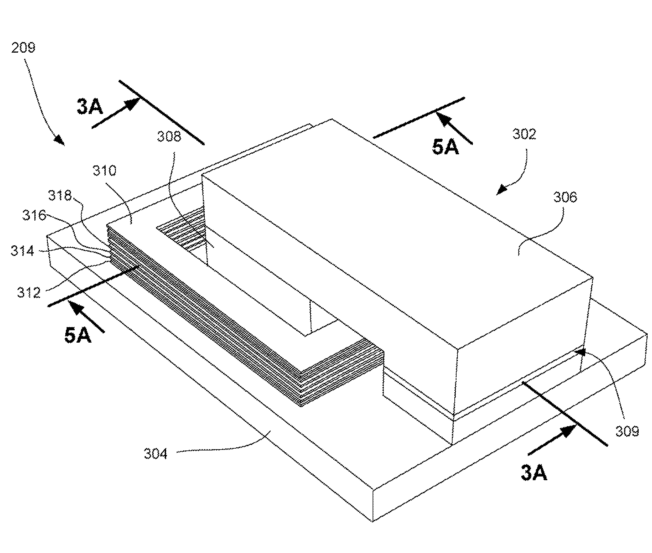
[0032]The embodiments described below disclose a new write transducer design for magnetic recording of all types, in which coils are wrapped around a bobbin portion of the yoke. Some of the advantages that, may be provided by some or all of the various embodiments are compact size, tight spacing of adjacent write transducers on wafer and on multi-transducer head, high efficiency and bandwidth, low inductance, low eddy current losses, and the...


PUM

PropertyMeasurementUnit
widthsaaaaaaaaaa
thicknessaaaaaaaaaa
widthaaaaaaaaaa

Abstract

A magnetic write transducer includes a yoke having a lower pole portion, an upper pole portion, and a first bobbin portion; a first coil turn wrapped around the first bobbin portion of the yoke in a first plane; a second coil turn wrapped around the first bobbin portion of the yoke in a second plane above the first plane; a third coil turn wrapped around the First bobbin portion of the yoke in a third plane above the second plane; and a fourth coil turn wrapped around the first bobbin portion of the yoke in a fourth plane above the third plane.

Description

FIELD OF THE INVENTION[0001]The present invention relates to magnetic head structures, and more particularly, this invention relates to a magnetic head structure having multiple modules.BACKGROUND OF THE INVENTION[0002]Business, science and entertainment applications depend upon computers to process and record data, often with large volumes of the data being stored or transferred to nonvolatile storage media, such as magnetic discs, magnetic tape cartridges, optical disk cartridges, floppy diskettes, or floptical diskettes. Typically, magnetic tape is the most economical and convenient means of storing or archiving the data. Storage technology is continually pushed to increase storage capacity and storage reliability. Improvement in data storage densities in magnetic storage media, for example, has resulted from improved medium materials, improved magnetic read / write heads, improved error correction techniques and decreased areal bit sizes. The data capacity of half-inch magnetic ta...

Claims


Application Information

Patent Timeline
Patent Type & Authority Patents(United States)
IPC IPC(8): G11B5/17H01L27/08H01F5/00
CPCG11B5/17G11B5/3123G11B5/584
Inventor BISKEBORN, ROBERT GLENNKIRSCHENBAUM, LEIF STEFAN
Owner INT BUSINESS MASCH CORP
Why Eureka
Try Eureka