System identification device

a technology of system identification and identification device, which is applied in the direction of adaptive control, force/torque/work measurement apparatus, instruments, etc., can solve the problem of inability to identify the restricted movement range, and achieve the effect of suppressing the influence, small operation, and suppressing the influence of constant torque disturban

Inactive Publication Date: 2011-08-23
YASKAWA DENKI KK
View PDF5 Cites 7 Cited by
  • Summary
  • Abstract
  • Description
  • Claims
  • Application Information

AI Technical Summary

Benefits of technology

[0086]According to the first aspect of the invention, it is possible to suppress the influence of a constant torque disturbance and to identify an inertia moment in an electric motor and a viscous friction through only a very small operation in a speed control system having any linear control law.
[0087]According to the second aspect of the invention, moreover, it is possible to suppress the influence of a constant torque disturbance and to identify an inertia moment in an electric motor and a viscous friction through only a very small operation in a position control system having any linear control law.
[0088]According to the third, ninth and tenth aspects of the invention, furthermore, it is possible to suppress the influence of a constant torque disturbance and to identify an inertia moment in an electric motor and a viscous friction through only a very small operation for any linear control law using any periodic speed command or periodic position command.
[0089]According to the fourth, eleventh and twelfth aspects of the invention, moreover, it is possible to suppress the influence of a constant torque disturbance, to control the influence of a noise in a torque command and to identify an inertia moment in an electric motor and a viscous friction through only a very small operation for any linear control law using any periodic speed command or periodic position command.
[0090]According to the fifth and sixth aspects of the invention, furthermore, it is possible to suppress the influence of a constant torque disturbance and to identify an inertia moment in an electric motor and a viscous friction through only a very small operation in a short time for any linear control law using an optional periodic speed command or periodic position command.
[0091]According to the seventh, eighth, thirteenth and fourteenth aspects of the invention, moreover, it is possible to suppress the influence of a constant torque disturbance and to identify an inertia moment in an electric motor and a viscous friction through only a very small operation in a short time for any linear control law using any periodic speed command or periodic position command through only a simple calculation.

Problems solved by technology

For this reason, there is a problem in that a sufficiently large movable range is required for identifying an inertia moment, and an inertia moment of an electric motor having a movable range restricted cannot be identified.

Method used


Image

  • System identification device
  • System identification device
  • System identification device

Examples


first example

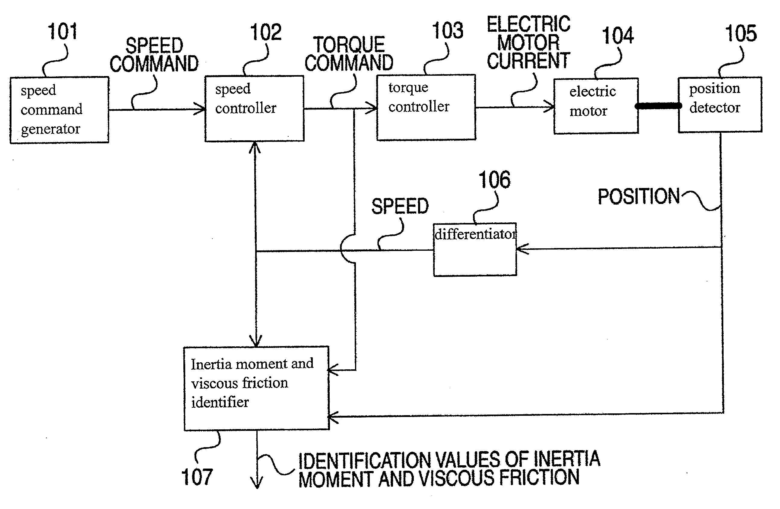
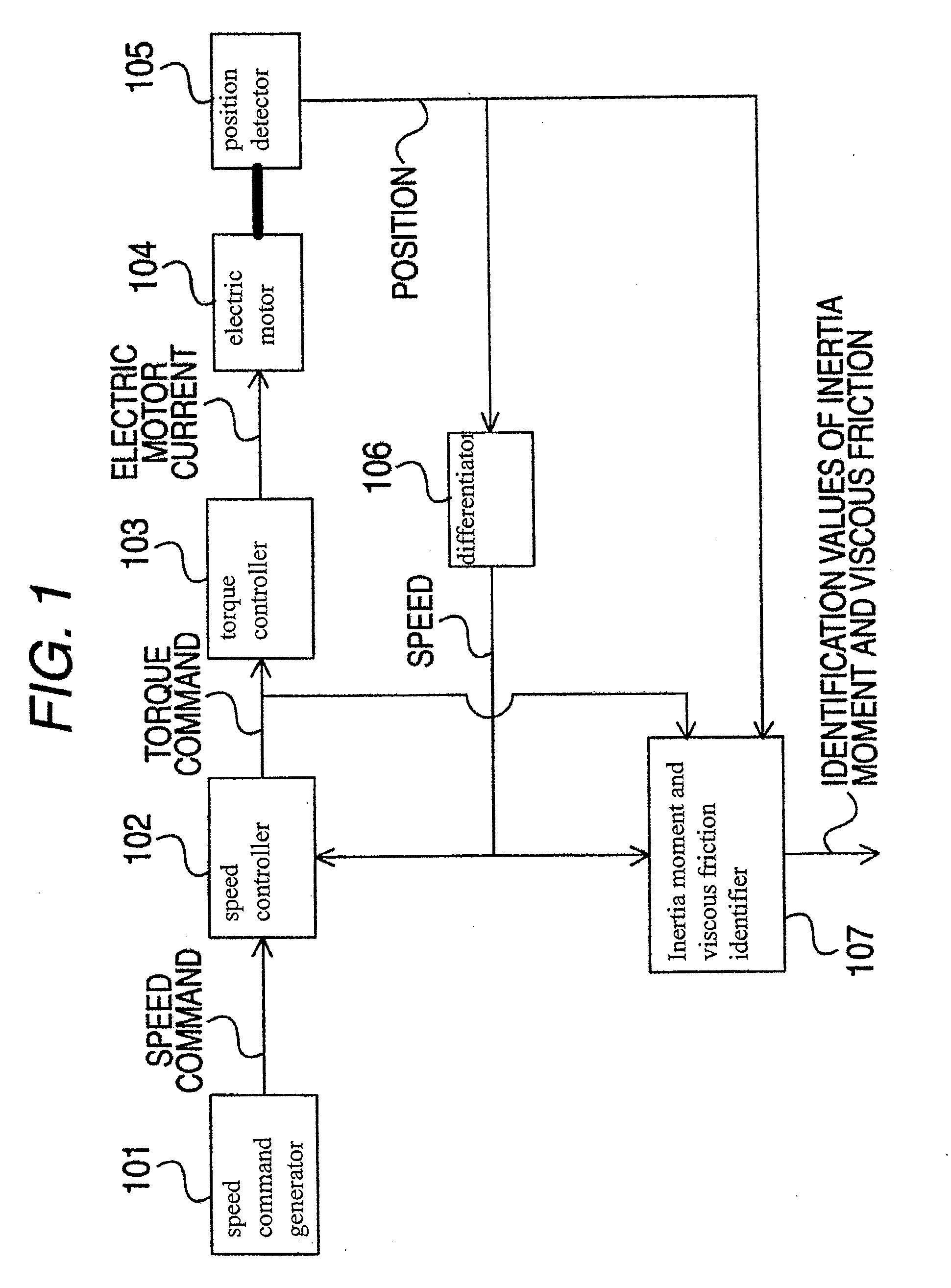
[0125]FIG. 1 is a block diagram showing a system identification device according to a first example.

[0126]In FIG. 1, 101 denotes a speed command generator, 102 denotes a speed controller, 103 denotes a torque controller, 104 denotes an electric motor, 105 denotes a position detector, 106 denotes a differentiator, and 107 denotes an inertia moment and viscous friction identifier.

[0127]A structure of the system identification device in the first example will be described below with reference to FIG. 1.

[0128]The speed command generator 101 outputs a speed command. The speed controller 102 inputs the speed command and a speed and then outputs a torque command. The torque controller 103 inputs the torque command and then outputs an electric motor current. The electric motor 104 is driven with the electric motor current and the position detector 105 detects and outputs a position thereof. The differentiator 106 inputs the position and then outputs the speed. The inertia moment and viscou...

second example

[0151]FIG. 3 is a block diagram showing a system identification device according to a second example.

[0152]In FIG. 3, 102 denotes a speed controller, 103 denotes a torque controller, 104 denotes an electric motor, 105 denotes a position detector, 106 denotes a differentiator, 107 denotes an inertia moment and viscous friction identifier, 301 denotes a position command generator, and 302 denotes a position controller.

[0153]A structure of the system identification device according to the second example will be described below with reference to FIG. 3.

[0154]The position command generator 301 outputs a position command. The position controller 302 inputs the position command and a position and then outputs a speed command. The speed controller 102 inputs the speed command and a speed and then outputs a torque command. The torque controller 103 inputs the torque command and then outputs an electric motor current. The electric motor 104 is driven with the electric motor current, and the p...

third example

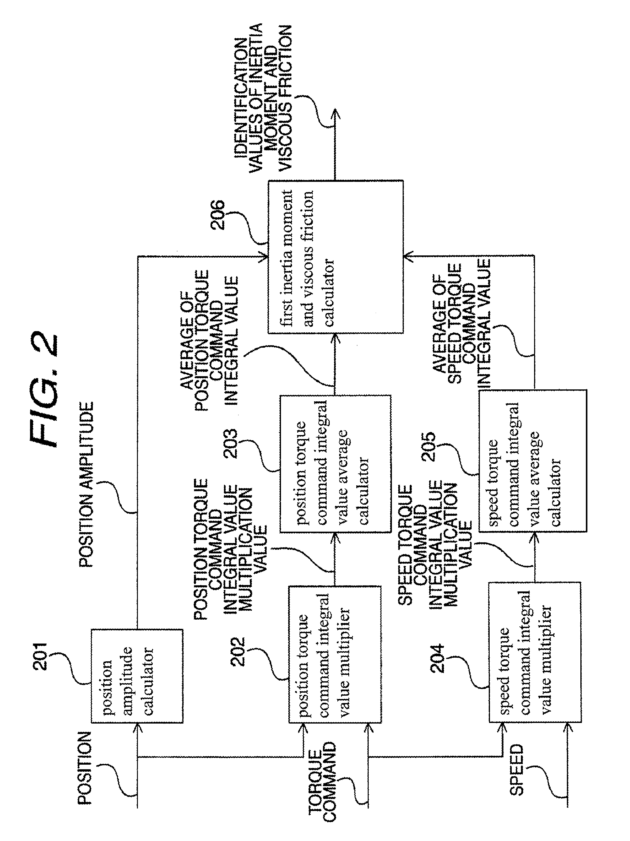
[0168]The third example is different from the first and second examples in that the third example employs a structure in which a position torque command integral value multiplier 202 and a speed torque command integral value multiplier 204 use a 1st-order time integral value of a torque command in place of a 0th-order time integral value of the torque command. Since other structures are the same as those in the first and second examples, description thereof will be omitted.

[0169]First of all, the principle of the example will be described with reference to FIGS. 1, 2 and 3.

[0170]An equation of motion of an open loop system including a torque controller 103, an electric motor 104 and a position detector 105 is represented by the Equation (7) according to the first example, where an inertia moment of the electric motor 104 is represented by J, a viscous friction is represented by D, a torque command is represented by Tref, a constant torque disturbance is represented by w and a posit...


PUM

PropertyMeasurementUnit
viscous frictionaaaaaaaaaa
speedaaaaaaaaaa

Abstract

A system identification device having a position amplitude calculator outputting a position amplifier; a position torque command integral value multiplier outputting a position torque command integral value multiplication value; a position torque command integral value average calculator inputting the position torque command integral value multiplication value and then outputting an average of a position torque command integral value; a speed torque command integral value multiplier outputting a speed torque command integral value multiplication value; a speed torque command integral value average calculator inputting the speed torque command integral value multiplication value and then outputting an average of a speed torque command integral value; and a first inertia moment and viscous friction calculator calculating identification values of inertia moment and viscous friction from the position amplitude, the average of the position torque command integral value and the average of the speed torque command integral value.

Description

TECHNICAL FIELD[0001]The present invention relates to a system identification device for identifying an inertia moment in an electric motor and a viscous friction.BACKGROUND ART[0002]A system identification device according to the related art identifies an inertia moment of a control target by dividing, by an integral time of an integrator, a steady-state value of a command torque difference Nth-order integral value to be an Nth-order time integral value of a signal obtained by subtracting an equivalent IP control system command torque from a PI control system command torque (see e.g., Patent Document 1).[0003]FIG. 8 is a block diagram showing a system identification device according to the related art.[0004]In FIG. 8, 801 denotes a first mixer, 802 denotes a proportional amplifier, 803 denotes an integrator, 804 denotes a second mixer, 805 denotes a control target, 806 denotes a control target Coulomb friction, 807 denotes a first-order lag filter, and 808 denotes an Nth-order inte...

Claims


Application Information

Patent Timeline
Patent Type & Authority Patents(United States)
IPC IPC(8): G01L1/00G01P3/00G01L3/00G01L5/00G01C19/00H02P29/00G05B13/02
CPCH02P23/14G05B13/02G01L5/00
Inventor ANDOH, FUKASHINAKAMURA, HIROSHI
Owner YASKAWA DENKI KK
Why Eureka
Try Eureka