
Protective module using electric current to protect objects against threats, especially from shaped charges

a technology of protection module and electric current, which is applied in the field of protection module using electric current, can solve the problems of widening the cross section of the jet, no adequate way to disturb and disturbing the jet, so as to improve the disintegration effect of the shaped charge j

Inactive Publication Date: 2011-08-30
FRAUNHOFER GESELLSCHAFT ZUR FOERDERUNG DER ANGEWANDTEN FORSCHUNG EV
View PDF20 Cites 7 Cited by
  • Summary
  • Abstract
  • Description
  • Claims
  • Application Information

AI Technical Summary

Benefits of technology

[0015]The present invention is a device for protecting an object against shaped charge jets comprising an electrode arrangement provided with at least one electrode facing the object and at least one electrode facing away from the object, between which electrodes an electrical voltage can be applied in such a manner that distinct improvement of the disintegration effect on the shaped charge jet is possible, comparable to a wire explosion. The measures required for this should fulfill the aspect of simple technological and cost-effective realization and, in particular, are realizable with as light a weight as possible.
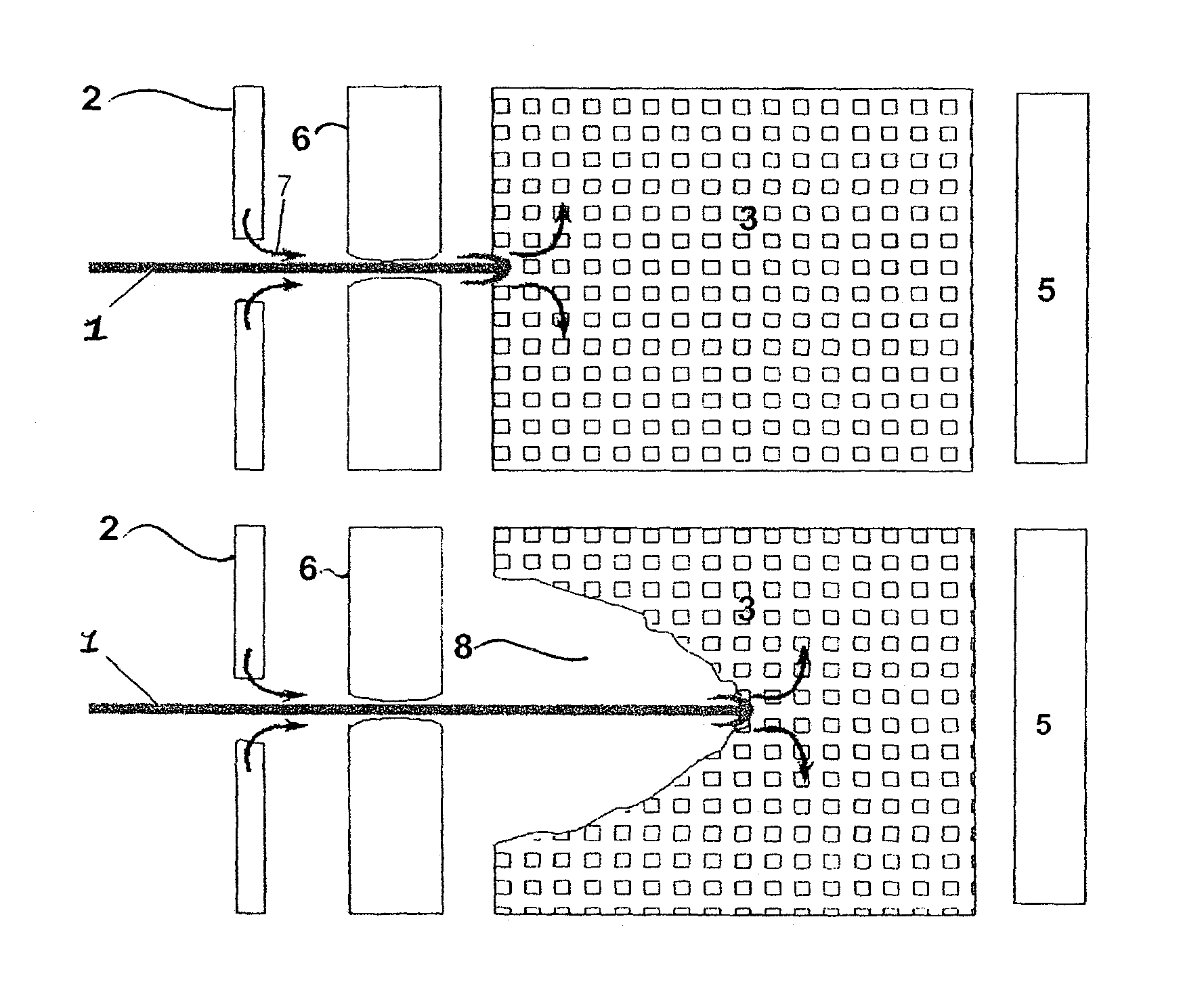
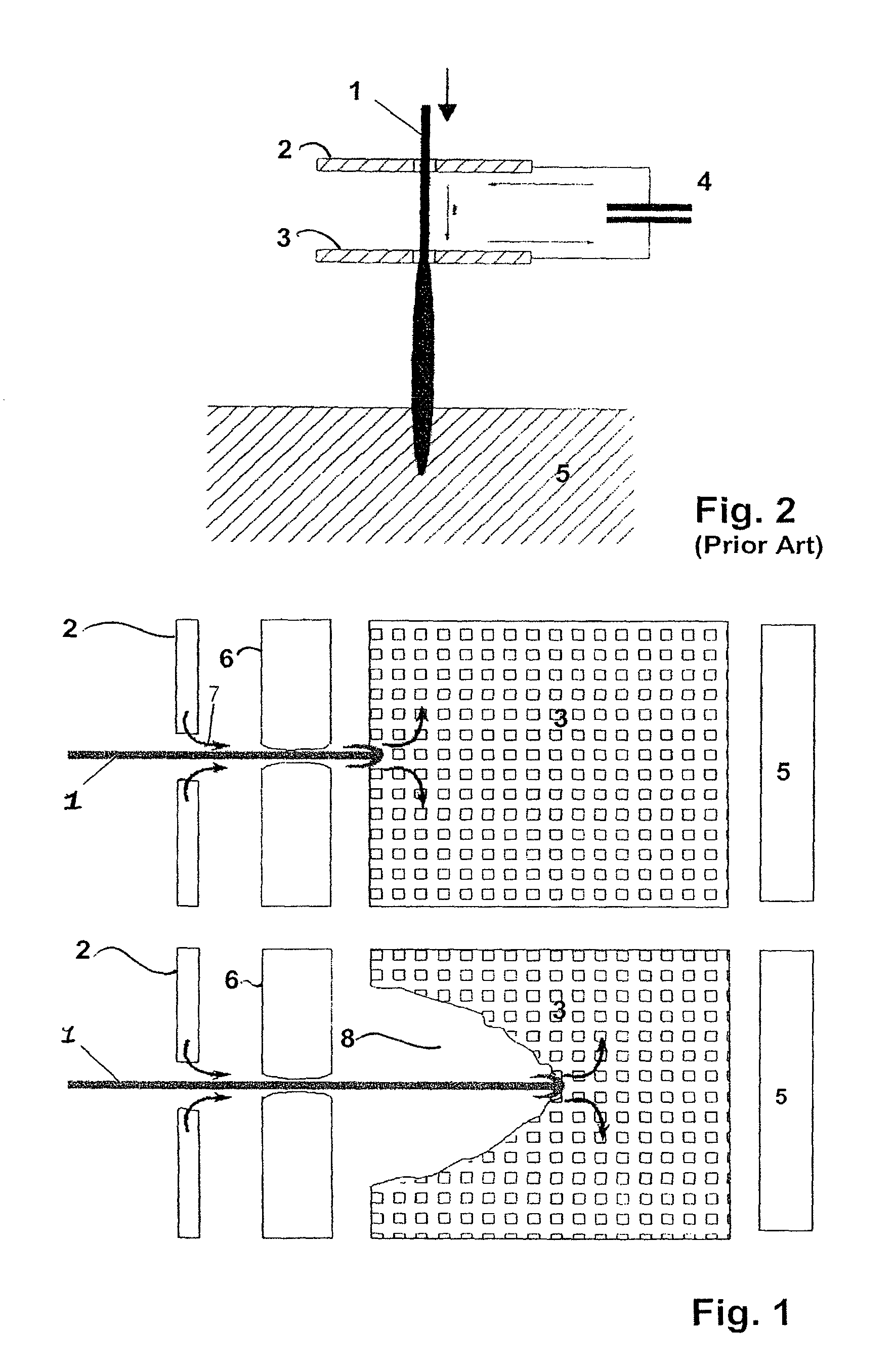
[0019]Apart from the reduced density of the heterogeneous region of the electrode facing the object, the region hit by the shaped charge jet reacts, contrary to full material such as steel, with great displacement of the heterogeneous electrode material away from the axis of the jet. The result is that the distance of the stationary heterogeneous electrode material in the radial direction from the axis of the jet—increases while the tip of the shaped charge jet penetrates further into the heterogeneous region of the electrode material, with a forming of a forward moving crater bottom. The tip of the jet develops in the region of the crater bottom a good electrical contact via which a high current can be coupled into the shaped charge jet. The coupled current at the crater bottom is able to contribute to disturbing the entire jet cross section from the tip of the shaped charge jet to the first electrode 2. At the same time, due to the great distance of the shaped charge jet from the material pushed aside by the passage of the jet tip, it is to be expected that coupling of current in jet regions behind the tip is reduced, thereby decreasing current paths that do not contribute to disintegration of the shaped charge jet to the tip of the jet.
[0020]In contrast to this, with a full material a solid crater wall forms which is only a small distance from the shaped charge jet thereby facilitating coupling in current behind the tip. The respective current paths no longer lead via the tip of the shaped charge jet thus detracting from effective disturbance of the jet tip.
[0021]It was demonstrated that the structure of the electrode material according to the invention using the aforedescribed material variants permits effectively influencing the tip of the shaped charge jet due to the material-based crater formation and the current paths developing therein.

Problems solved by technology

A basic principle of this electric protective mechanism is coupling an electric current into the jet generated by the shaped charge with the aid of two electrode plates, which then results in disturbing the jet.
For this reason, especially the time span of coupling-in the current into the tip of the shaped charge jet is very short and consequently also the possibility of widening the cross section of the jet, as the current is only able to rise at a limited rate of change which is essentially dependent on the inductivity of the circuit.
Thus there is presently no adequate way to disturb the shaped charge jet with state-of-the art means of effective protection from shaped charge jets.

Method used


Image

  • Protective module using electric current to protect objects against threats, especially from shaped charges
  • Protective module using electric current to protect objects against threats, especially from shaped charges

Examples


Embodiment Construction

[0026]FIG. 1 shows a schematic principle representation of the arrangement designed according to the invention for protection from shaped charge jets. The two picture sequences depicted in FIG. 1 each show a shaped charge jet 1 penetrating a front electrode 2 facing away from the object 5 from the left and then propagating to the right. In the jet direction of the shaped charge jet 1, a stripper plate 6 made of an electrically insulating material, which can for example be made of polypropylene, is placed downstream of the electrode 2. Moreover, an electrode facing the object, a so-called rear electrode 3 is provided which in the depicted preferred embodiment is designed to be porous and encloses single cavities as the multiplicity of small boxes principally indicates. The upper sequential representation in FIG. 1 shows the moment in time when the shaped charge jet 1 contacts the rear electrode 3 and in this manner produces an electrical contact between the front electrode 2 and the ...


PUM


Abstract

A device is disclosed for protecting an object from shaped charge jets comprising an electrode arrangement which is provided with at least one electrode facing the object and one electrode facing away from the object between which an electrical voltage can be applied. The invention is distinguished by the object-facing electrode having at least one area with a spatially heterogeneous electrode material.

Description

BACKGROUND OF THE INVENTION[0001]1. Field of the Invention[0002]The present invention relates to a protective module using electric current to protect objects against threats, especially from shaped charges.[0003]2. Description of the Prior Art[0004]Various protective mechanisms are already in use to protect objects, for example combat tanks, from shaped charges. One protective mechanism provides for using electric current to disturb shaped charge jets. A basic principle of this electric protective mechanism is coupling an electric current into the jet generated by the shaped charge with the aid of two electrode plates, which then results in disturbing the jet.[0005]Shaped charge jets are generated with the detonation of an arrangement of highly explosive substances about a conic or hemispherical intermediate metal ply and are especially suited for penetrating armor. Such type shaped charge jets are distinguished by a unidirectional aimed material jet developing in the course of the...

Claims


Application Information

Patent Timeline
Patent Type & Authority Patents(United States)
IPC IPC(8): F41H11/00
CPCF41H5/007
Inventor WICKERT, MATTHIASMICHAEL, KARSTENKUDER, JURGEN
Owner FRAUNHOFER GESELLSCHAFT ZUR FOERDERUNG DER ANGEWANDTEN FORSCHUNG EV
Learn More