Energy distributing side structure for vehicle side impact occupant protection

a technology for side impact protection and energy distribution, which is applied in the direction of roofs, transportation and packaging, vehicle arrangements, etc., can solve the problems of high door speed, severe load on the structural members of the body, and cross members that have not been involved in the management of crash-related energy, so as to reduce the amount of distortion and less energy

Active Publication Date: 2011-08-30
FORD GLOBAL TECH LLC
View PDF8 Cites 48 Cited by
  • Summary
  • Abstract
  • Description
  • Claims
  • Application Information

AI Technical Summary

Benefits of technology

[0011]The disclosed side structure is able to manage laterally directed loads. On impact, the pillar experiences a bending moment about the rocker to which it is connected. Load is transferred to the cross-member supporting the rear of the front seat and the cross-member transfers the load to the tunnel brace. The tunnel brace in turn transfers load to the non-impacted side of the vehicle. Thus the present device allows the vehicle's body cross-member to react in a more controlled manner against such laterally imposed loads. According to the disclosed configuration the side structure absorbs less energy by distributing load to the surrounding vehicle and thus endures a reduced amount of distortion.

Problems solved by technology

The side impact event imposes severe loading on the structural members of the body.
This situation is complicated by the fact that many compact or mid-sized vehicles have low rocker heights that may pass below the bumper of an impacting vehicle, resulting in high door velocities.
Although automotive bodies used in conventional body-on-frame construction have typically used cross members for decades, such cross members have not been involved in the management of crash-related energy.
This arrangement created a package problem for occupant foot space in the rear seat.
On the other hand, if the structure is part of the seat then gaps are required between the structure in the seat and the B-pillar and the center console.
This arrangement does not effectively take a load until after the deformation of the vehicle occurs.

Method used


Image

  • Energy distributing side structure for vehicle side impact occupant protection
  • Energy distributing side structure for vehicle side impact occupant protection
  • Energy distributing side structure for vehicle side impact occupant protection

Examples


Embodiment Construction

[0019]In the following figures, the same reference numerals will be used to refer to the same components. In the following description, various operating parameters and components are described for different constructed embodiments. These specific parameters and components are included as examples and are not meant to be limiting.

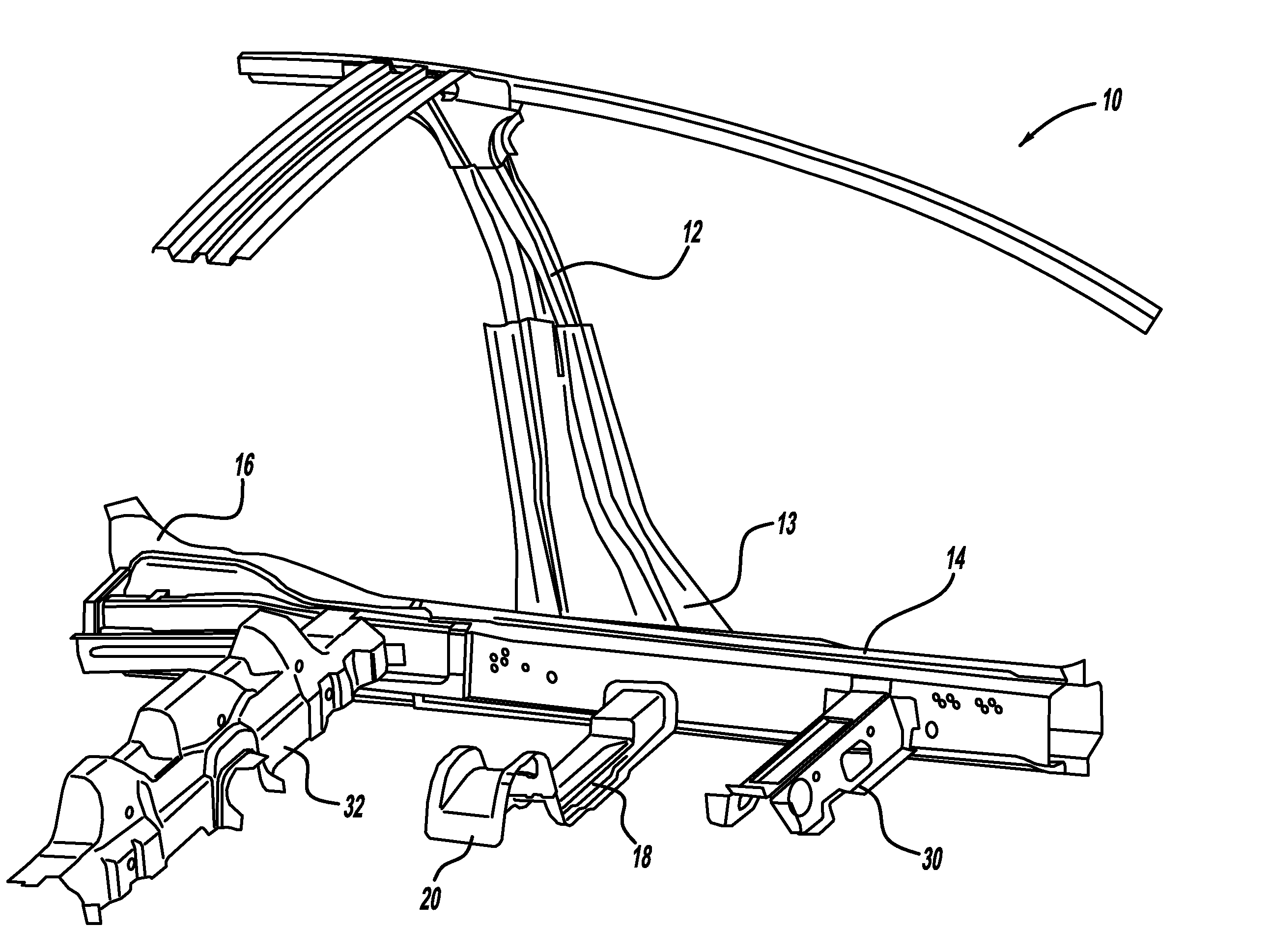
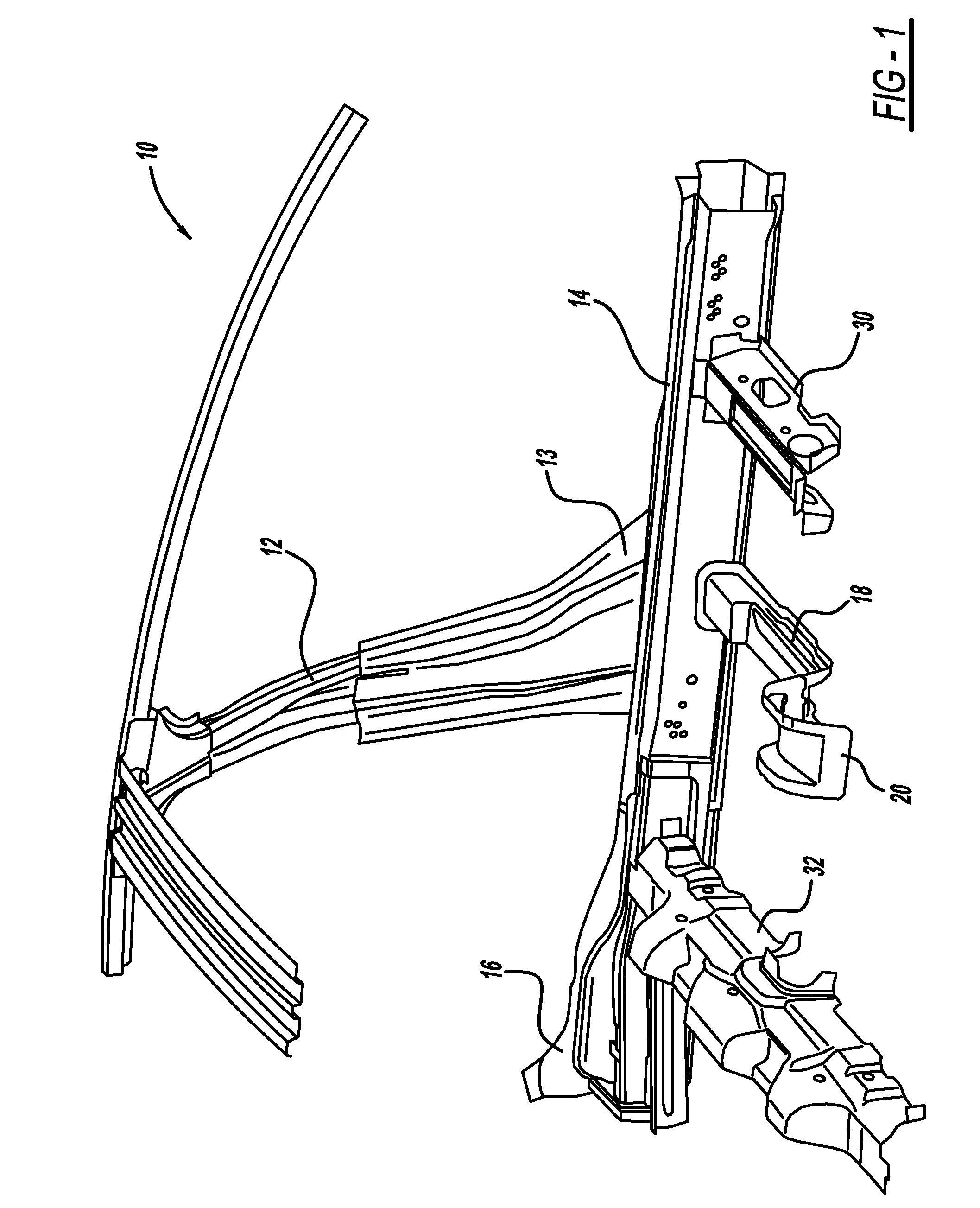
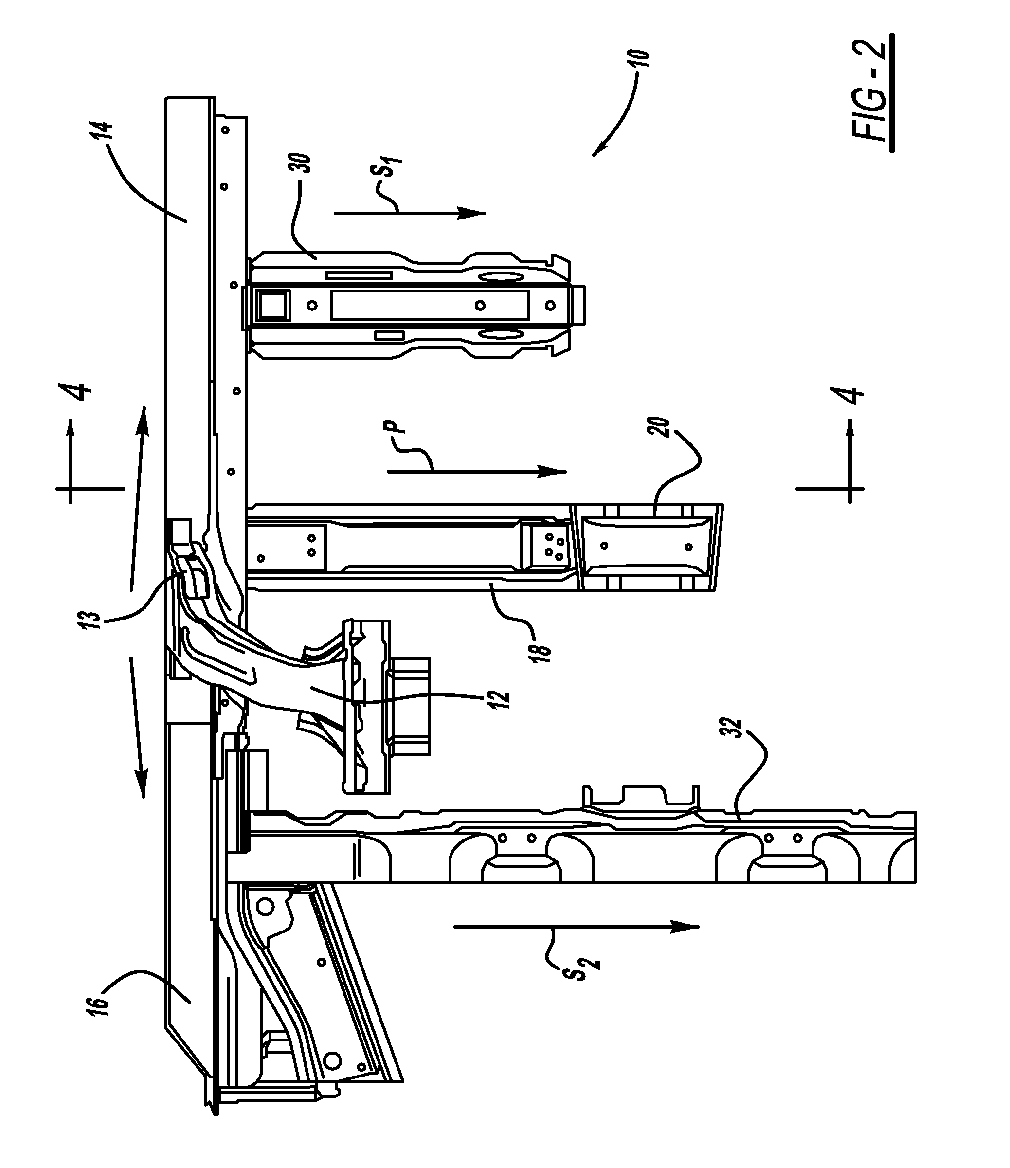
[0020]FIG. 1 shows a perspective view of a load distributing structure of the disclosed invention, generally illustrated as 10. FIG. 2 illustrates a top plan view of the load distributing structure 10. FIG. 3 provides a side elevational view of the load distributing structure 10.

[0021]With reference to FIGS. 1, 2 and 3, the load distributing structure 10 includes a pillar, such as the illustrated B-pillar 12, and a rocker 14. The B-pillar 12 has a wide base 13. The rocker 14 is preferably composed of high strength steel and is more preferably composed of ultra-high strength steel to minimize rocker twisting in the event of a side impact. The placement and c...


PUM


Abstract

An energy distributing side structure for a vehicle is disclosed. The side structure includes a B-pillar having a wide base and an internal reinforcing tube, a rocker having an internal bulkhead, a rear rocker, and at least one cross-member extending vehicle-inward from the rocker. The cross-member may extend to the vehicle tunnel and may be attached to a tunnel brace. One or more additional cross-members may be provided which also extend vehicle-inward from the rocker and define secondary load paths. By this arrangement loading is transferred to the floor and cross-members of the vehicle during a lateral impact event.

Description

TECHNICAL FIELD[0001]The disclosed invention relates to a side structure for an automotive vehicle. More particularly, the disclosed invention relates to a side structure for a vehicle which incorporates a B-pillar having a wide base and an internal reinforcing tube, a rocker having a bulkhead, at least one cross-member, and rear rocker webbing. According to the side structure of the disclosed invention loading is transferred to the floor and cross-members of the vehicle during an impact event.BACKGROUND OF THE INVENTION[0002]Side impact events involving automotive vehicles typically include the imposition of dynamic loading to the vehicle body sides. The side impact event imposes severe loading on the structural members of the body. This situation is complicated by the fact that many compact or mid-sized vehicles have low rocker heights that may pass below the bumper of an impacting vehicle, resulting in high door velocities.[0003]Although automotive bodies used in conventional bod...

Claims


Application Information

Patent Timeline
Patent Type & Authority Patents(United States)
IPC IPC(8): B60N99/00
CPCB62D21/157B62D25/025
Inventor CRAIG, RYAN
Owner FORD GLOBAL TECH LLC
Why Eureka
Try Eureka