Lighting device having LED light bars

a technology of led light bars and light fixtures, which is applied in the direction of light support devices, fixed installations, lighting and heating apparatus, etc., can solve the problems of high cost of repair, low luminous efficiency, and high power consumption, and achieves effective heat dissipation, easy to vary the illumination area, and easy to repair

Inactive Publication Date: 2011-08-30
ANTEYA TECH CORP
View PDF1 Cites 44 Cited by
  • Summary
  • Abstract
  • Description
  • Claims
  • Application Information

AI Technical Summary

Benefits of technology

[0012]The main objective of the invention is to provide an LED light bar type lighting device that is easy to repair, effectively dissipates heat and easy to vary illumination area.
[0017]1. Easy to repair: Each light bar is detachably mounted on the light-bar mount. With the module design, it can reduce the weight, save material cost and easy to install. Technicians only need to change a broken one of the light bars without dismount the whole light-bar mount. Therefore, the cost of repair is low.
[0018]2. Independent heat-dissipating structure: Each light bar has a respective heat sink and high-power LED modules are mounted on the heat sink. Therefore each light bar uses a single heat-dissipating structure and can dissipate heat more effectively. This design can prevent the high-power LED modules from over-heating in high temperature and thus has a long lifetime. With the independent module heat-dissipating structure, the main device has flexible shape design without needing of considering the heat-dissipating issue.
[0019]Another objective of the invention is to provide a lighting device that is easy to vary illumination area. The light-bar mount of the lighting device is integrally formed by a board being bent into multiple portions including a plane portion and at least one oblique portion being formed on and extending from an edge of the plane portion. The oblique portion has a slope relative to the plane portion. The light bars are respectively mounted on the plane portion and the at least on oblique portion. High-power LED modules mounted on the light bars are substantially arranged in a matrix. With the design of the different slopes of oblique portions, the lighting device can provide a relative wide, even, oval-shaped illumination area to meet requirements of being a streetlight. The high-power LED modules arranged in a matrix can perform a great visual effect when lighting.
[0021]Another yet objective of the invention is to provide a lighting device having at least one ornamental light bar with a control circuit board and at least one multi-color high-power LED module. The control circuit board takes frequency of a utility AC power source as a synchronous signal for all ornamental light bars. The frequency is sensed by an AC frequency sampling circuit and the multi-color type high-power LED module is activated to achieve a simultaneous color changing effect for a long time.

Problems solved by technology

Conventional incandescent bulbs are gradually being replaced in many applications by LED light source because incandescent bulbs have disadvantages of high power consumption, low luminous efficiency, and being renewed frequently due to a short life span.
1. Not easy to repair: since the high-power LED modules are soldered on the aluminum circuit board, when one of the high-power LED modules fails, a normal person cannot only change the broken one with simple tool such as a solder, but need a professional technician to disconnect the aluminum circuit board, and then sends the whole aluminum circuit board with the high-power LED modules or the full set of streetlight back to the factory for fixing. Therefore, the cost of repair is very high.
2. Low heat-dissipation efficiency: A large amount of high-power LED modules is required in a conventional LED lighting device, such as a streetlight, to provide sufficient lights. However, large amounts of heat are produced when activating high-power LED modules. When all the heats from each module are conducted to the heat-dissipating base, it will double the heat accumulating and cause heavy loading for the heat-dissipating base.
Due to consideration of installing the LED lighting device in a high position, the aluminum circuit board and the heat-dissipating base are normally limited in size and weight.
With such limitation, the LED lighting device is hard to effectively dissipating heat when the heat-dissipation base was not well designed.
Therefore, operating the high-power LED modules in high temperature without effective heat dissipation may eventually lead to device failure and may also result in overheating of other electronic components on the circuit board and shortening of their life spans.
Designing the structure to meet different kinds of illumination-area may require a lot of different molds and high cost.

Method used


Image

  • Lighting device having LED light bars
  • Lighting device having LED light bars
  • Lighting device having LED light bars

Examples


Embodiment Construction

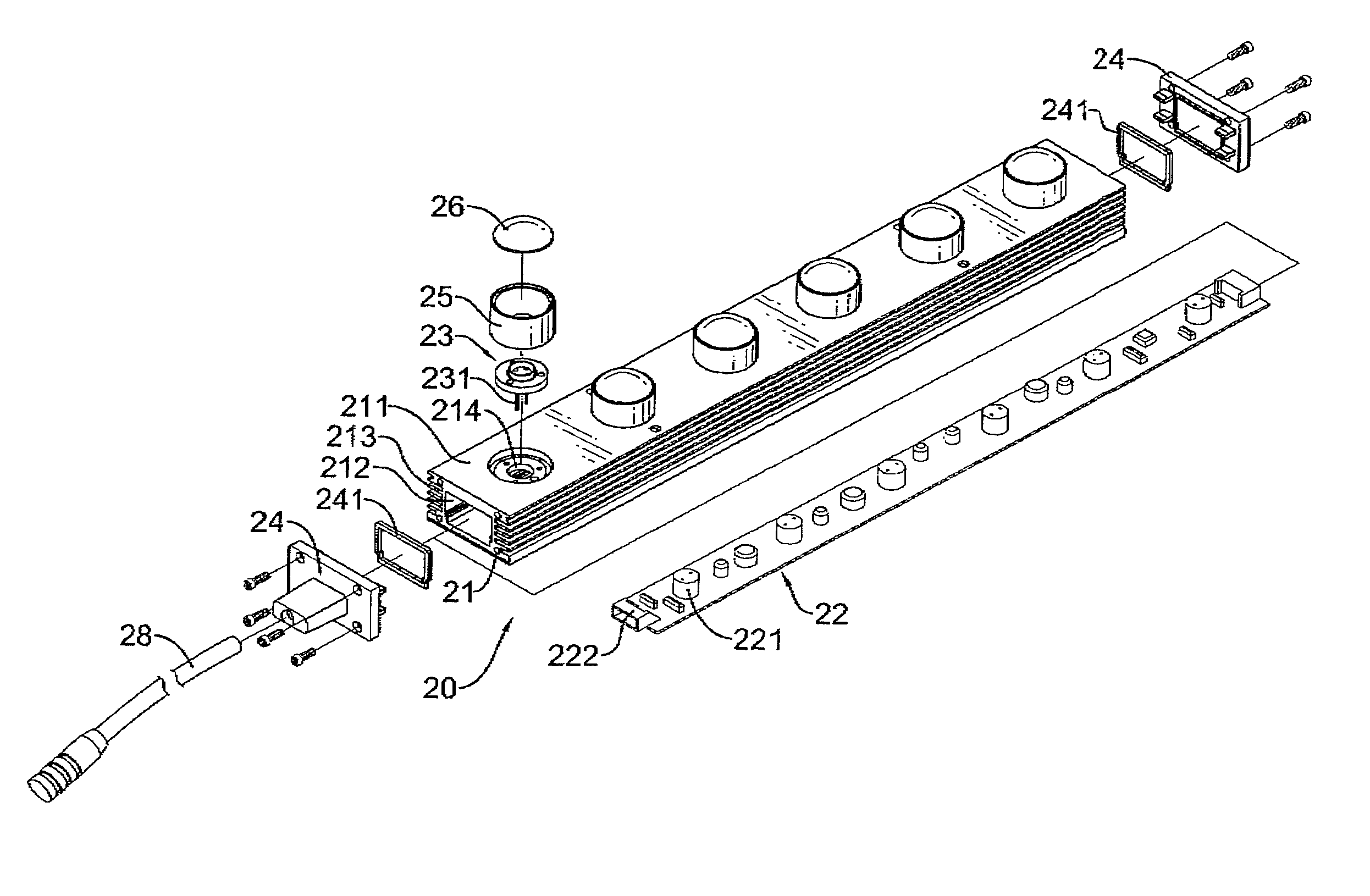
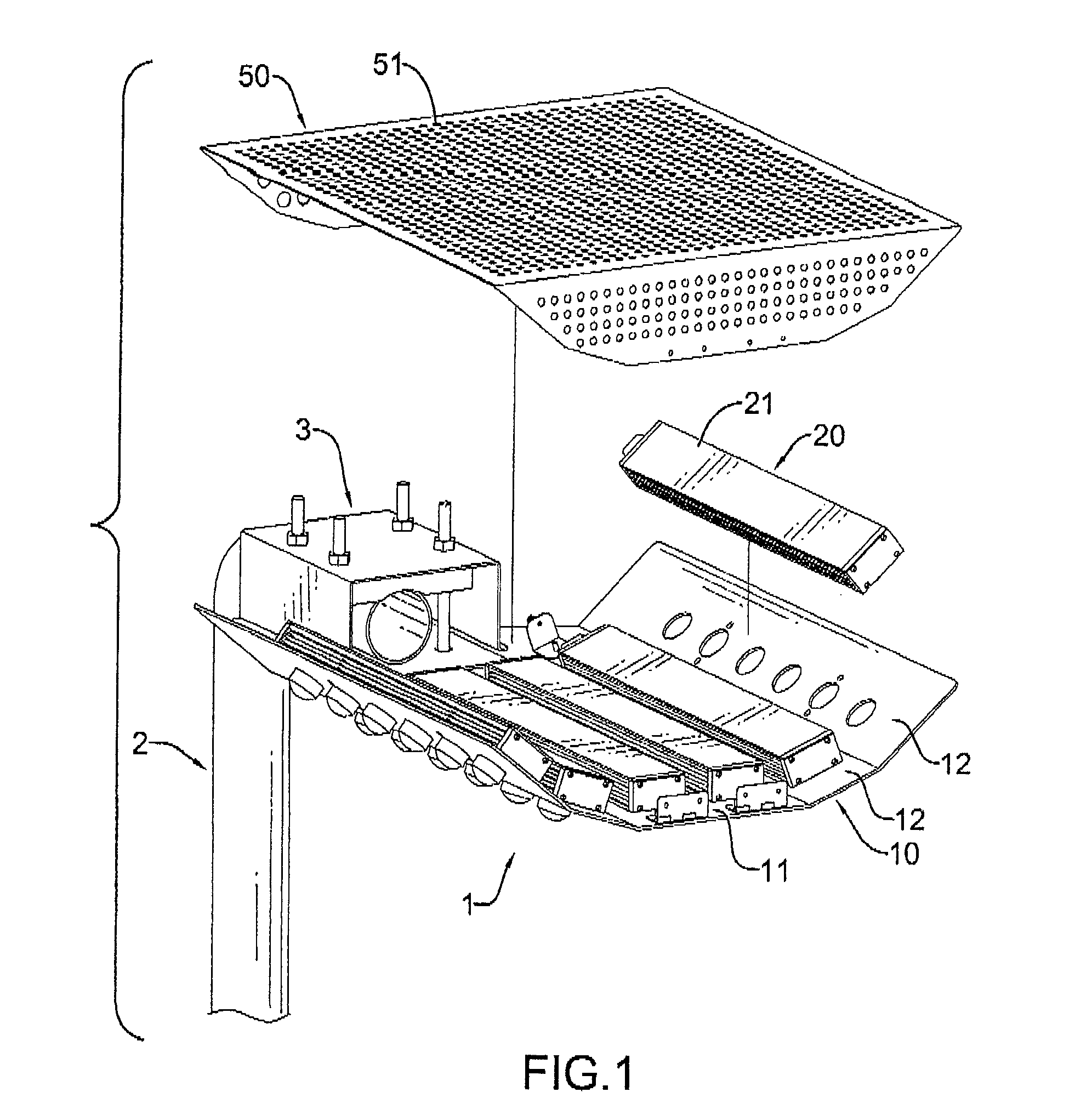
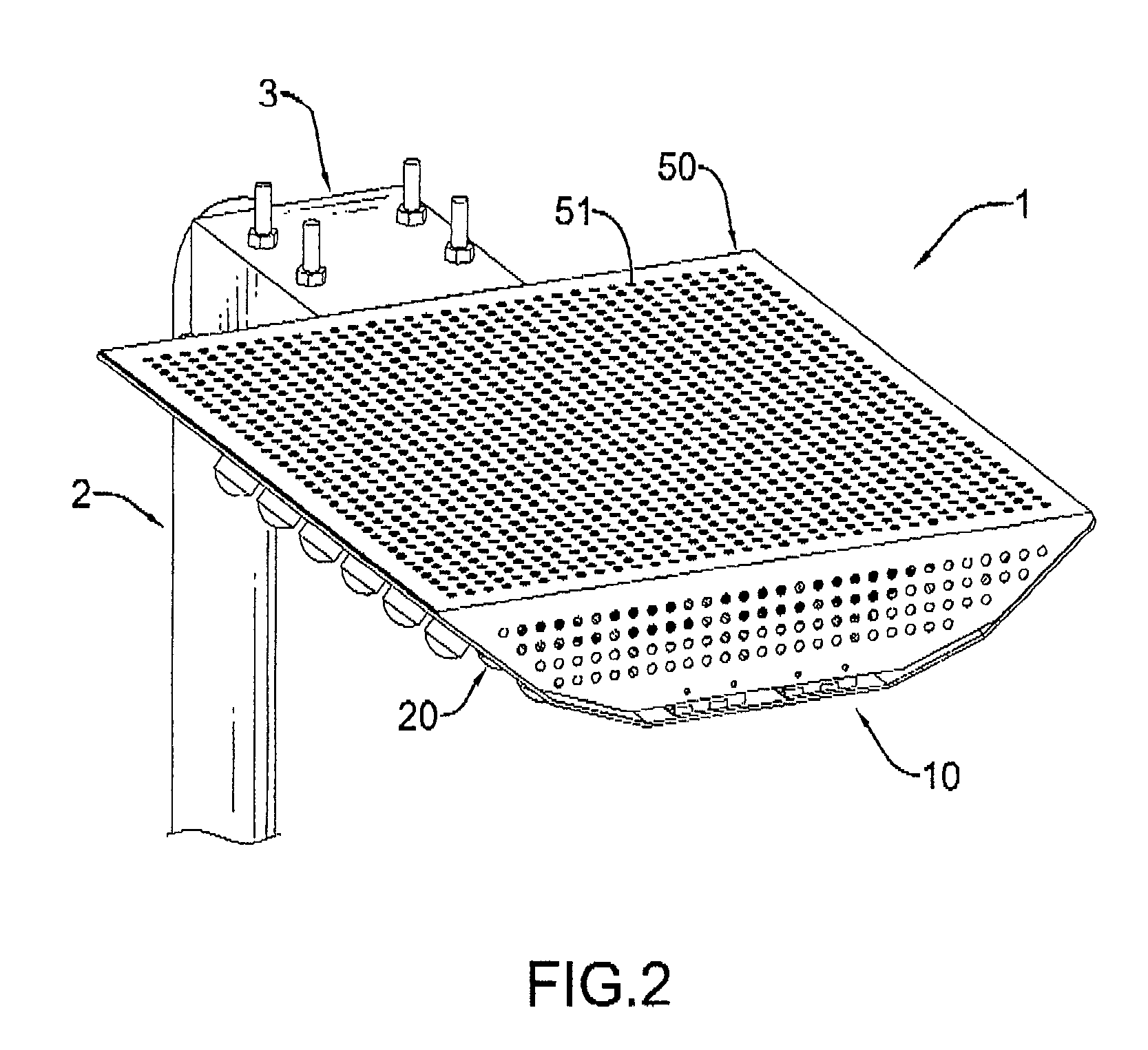
[0034]With reference to FIGS. 1 to 3, a lighting device (1) in accordance with the present invention comprises a light-bar mount (10) and multiple light bars (20) and may further include at least one ornamental light bar (30) as in FIG. 3 and a cover (50) as in FIGS. 1 and 2.

[0035]The light-bar mount (10) is integrally formed from a board and may be implement as a flat board or a board being bent into multiple portions. Preferably the light-bar mount (10) is integrally bent to have a plane portion (11), at least one oblique portion (12), two optional upstanding portions (13) and multiple optional mounting holes as shown in FIG. 3. The at least one oblique portion (12) is formed on and extends from an edge of the plane portion (11) and may be flat or arched. Preferably multiple oblique portions (12) are implemented and integrally extend from two opposite edges of the plane portion (11) sequentially and have two opposite outermost edges. Each of the oblique portions (12) has a slope r...


PUM


Abstract

A lighting device has a light-bar mount and multiple light bars. The light-bar mount is integrally formed from a board. The light bars are mounted on the light-bar mount and each light bar has a heat sink, a circuit board and multiple high-power LED modules. The heat sink is detachably mounted in the light-bar mount. The circuit board is mounted in the heat sink. The high-power LED modules are mounted on the heat sink and electrically connected to the circuit board for providing outward illumination.

Description

BACKGROUND OF THE INVENTION[0001]1. Field of the Invention[0002]The present invention relates to a lighting device, especially to a lighting device having multiple LED light bars.[0003]2. Description of the Related Art[0004]In recent years, lighting devices generally use incandescent bulbs or high-power LEDs as light sources. Conventional incandescent bulbs are gradually being replaced in many applications by LED light source because incandescent bulbs have disadvantages of high power consumption, low luminous efficiency, and being renewed frequently due to a short life span. Compared with the conventional incandescent bulbs, LEDs offer advantages of high efficiency, low power consumption and a relatively long lifetime.[0005]With reference to FIG. 11, a conventional LED lighting device applied as a streetlight may have a heat-dissipating base (42), an aluminum circuit board (41), multiple high-power LED modules (40) and a cover (43). The heat-dissipating base (42) has multiple fins....

Claims


Application Information

Patent Timeline
Patent Type & Authority Patents(United States)
IPC IPC(8): F21S4/00F21V21/00
CPCF21S8/086F21V15/01F21V23/04F21V29/004F21V29/83H05B33/0803G02B6/001F21V29/767F21S4/003F21V21/116F21Y2101/02Y02B20/72Y10S362/80F21W2131/103F21V21/30F21K9/20F21Y2103/10F21Y2115/10H05B45/30
Inventor WU, TING-FENGLIN, CHUN-HUNGTSENG, CHIH-HUNG
Owner ANTEYA TECH CORP
Why Eureka
Try Eureka