Supercharge Your Innovation With Domain-Expert AI Agents!

Method for grayscale display processing for multi-grayscale display to reduce false contours in a plasma display device

a plasma display device and multi-grayscale technology, applied in the field of grayscale display processing for multi-grayscale display to reduce false contours in plasma display devices, can solve the problems of false contours, significant insufficient grayscale expression of video images, and display quality degradation

Inactive Publication Date: 2011-08-30
MAXELL HLDG LTD
View PDF12 Cites 1 Cited by
  • Summary
  • Abstract
  • Description
  • Claims
  • Application Information

AI Technical Summary

Benefits of technology

The present invention provides a technology for PDP devices that carry out grayscale display processing. The technology aims to enhance display quality by reducing false contour and securing the number of grayscale levels. The technology involves using a subfield lighting pattern with multiple types of subfields in a field, where each subfield has a different lighting step. This arrangement helps to reduce the number of positions where an absence of light-on subfield exists and reduces the generation of false contour. The plurality of modes is arranged so as to change at as short intervals as possible spatially and further temporally, which eliminates undesirable patterns caused by a difference in brightness between the lighting steps. Overall, the technology improves display quality while suppressing the insufficiency of grayscale expression.

Problems solved by technology

In this case, the number of lighting steps (s) is only eleven in the first method, which is significantly insufficient for grayscale expression of the video image.
In other words, even when a structure for preventing an absence of light-on subfield in a subfield lighting pattern is simply adopted, a side effect of insufficiency of grayscale expression (the number of lighting steps (s)) occurs, and the display quality is thus deteriorated.
However, the position of the lighting step (s) where there is an absence of a light-on subfield becomes a cause of the false contour.

Method used


Image

  • Method for grayscale display processing for multi-grayscale display to reduce false contours in a plasma display device
  • Method for grayscale display processing for multi-grayscale display to reduce false contours in a plasma display device
  • Method for grayscale display processing for multi-grayscale display to reduce false contours in a plasma display device

Examples


first embodiment

[0040]A PDP device according to a first embodiment of the present invention will be described with reference to FIG. 1 to FIG. 5. In the first embodiment, the PDP device has a structure where two types (n=2) of SF lighting patterns are combined and each ½ thereof is equally arranged spatially so that the number of absences of light-on SF becomes half in the regions in the field by way of combination of the first and second methods. By this means, the level of false contour is reduced to half.

[0041]

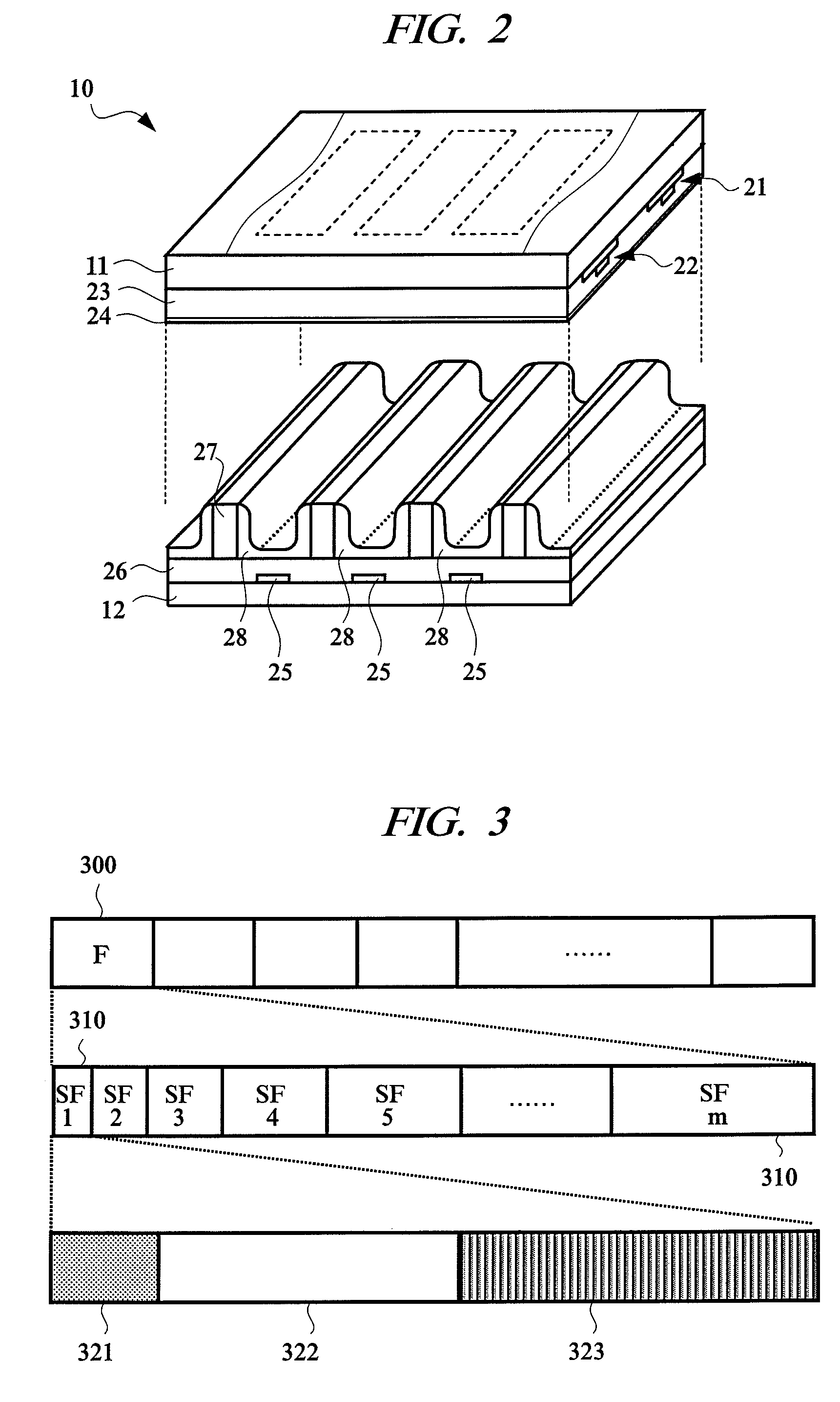
[0042]First, the basic structure will be described. The entire structure of the PDP device in each embodiment will be described with reference to FIG. 1. This PDP device has a structure including a display panel (PDP) 10, a control circuit 110, a driving circuit (driver) 120, and others. The control circuit 110 includes a grayscale display processing unit 111, a field memory unit 112, a timing generating unit 113, and others and it controls the entire PDP device including the driving circu...

second embodiment

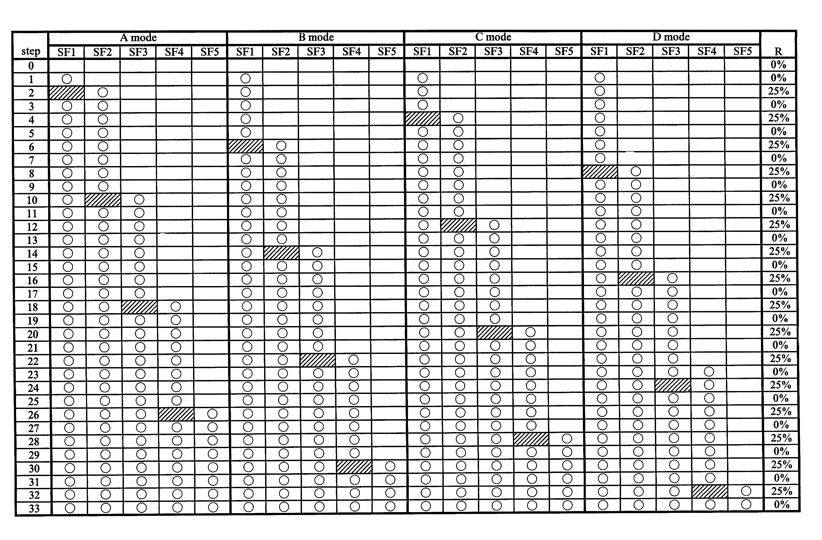
[0062]Next, a second embodiment will be described with reference to FIG. 6, FIG. 7 and others. The basic structure in the second embodiment is similar to that in the first embodiment, and four (n=4) types of SF lighting patterns (A, B, C, and D modes) can be selected in the regions of a field.

[0063]

[0064]FIG. 6 shows the spatial arrangement of these A to D modes in a field, in which the A to D modes are equally distributed so that different modes are repeated between adjacent pixels in units of blocks of two rows and two columns.

[0065]

[0066]FIG. 7 shows structures of the four types of the SF lighting patterns (the A to D modes) in the structure in FIG. 6. Further, in FIG. 7, if all lighting steps (s) are illustrated, the number thereof becomes too large, and therefore, only a portion of 34 lighting steps (s) that correspond to the lower five SFs (SF1 to SF5) is illustrated. Note that the remaining portion of the SFs (SF6 to SF10) has the similar structure.

[0067]For example, when pay...

third embodiment

[0071]Next, a third embodiment will be described with reference to FIG. 8 and others. The basic structure in the third embodiment is similar to that in the first embodiment. Further, in the structure of the third embodiment, spatial mode arrangements in fields of the two (n=2) types of the SF lighting patterns described above are inverted between the two (odd number and even number) fields.

[0072]

[0073]When paying attention to the step s=7 in the structure of spatial arrangement of the two (n=2) types of the A and B modes in FIG. 4 and FIG. 5 again, the SFs 1, 2, and 4 are in a light-on state in the A mode, and the SFs 1, 2, and 3 are in a light-on state in the B mode. In this case, it is assumed that the luminance ratios (weight) of the SF1 to SF4 are 1, 2, 4, and 8, respectively. Then, the total brightness of the light-on SFs in the A mode is 1+2+8=11, and that of the light-on SFs in the B mode is 1+2+4=7. Accordingly, the cells with brightness of 11 and 7 appear in a zigzag manner...


PUM


Abstract

In the PDP device, for example, two types of SF lighting patterns (A and B modes) are equally divided and arranged in spatially different regions in a field. For example, the patterns are arranged in a zigzag manner in units of pixels. At all lighting steps, existence of an absence of light-on SF which becomes a cause of false contour is permitted only in one mode. Accordingly, a generation rate of absence of light-on SF per field when the modes are combined is low, and the level of false contour can be reduced. Further, the spatial arrangement of each mode is optionally changed among the fields.

Description

CROSS-REFERENCE TO RELATED APPLICATION[0001]The present application claims priority from Japanese Patent Application No. JP 2006-226632 filed on Aug. 23, 2006, the content of which is hereby incorporated by reference into this application.TECHNICAL FIELD OF THE INVENTION[0002]The present invention relates to a technology for a display device that carries out grayscale display processing for multi-grayscale display. More particularly, it relates to a technology for reducing false contours (pseudo contours) of a moving picture on a plasma display device (PDP device) and others provided with a plasma display panel (PDP).BACKGROUND OF THE INVENTION[0003]Alternating current (AC) type PDP devices are widely used as a flat display. The PDP device carries out grayscale display processing for grayscale expressions by using an intra-frame time division method (subfield method). In the subfield method, a field (or frame) serving as a unit of a video image display which is displayed on a displa...

Claims


Application Information

Patent Timeline
Patent Type & Authority Patents(United States)
IPC IPC(8): G09G3/28G09G3/20G09G3/288G09G3/291G09G3/298H04N5/66
CPCG09G3/2025G09G3/2803G09G3/2077G09G2320/0261
Inventor ISHIDA, KATSUHIROYAMAMOTO, AKIRAKOJIMA, AYAHITOKUBO, SHINGOSHIIZAKI, TAKASHIKURIYAMA, HIROHITO
Owner MAXELL HLDG LTD
Features
  • R&D
  • Intellectual Property
  • Life Sciences
  • Materials
  • Tech Scout
  • Unparalleled Data Quality
  • Higher Quality Content
  • 60% Fewer Hallucinations
Learn More