Optical interconnection methods for high-speed data-rate optical transport systems

Inactive Publication Date: 2011-08-30
CORNING OPTICAL COMM LLC
View PDF9 Cites 72 Cited by
  • Summary
  • Abstract
  • Description
  • Claims
  • Application Information

AI Technical Summary

Problems solved by technology

This is potentially problematic because existing network systems and some planned for high-speed data-rate optical transport systems are based on 12-fiber MPO connectors.

Method used


Image

  • Optical interconnection methods for high-speed data-rate optical transport systems
  • Optical interconnection methods for high-speed data-rate optical transport systems
  • Optical interconnection methods for high-speed data-rate optical transport systems

Examples


Embodiment Construction

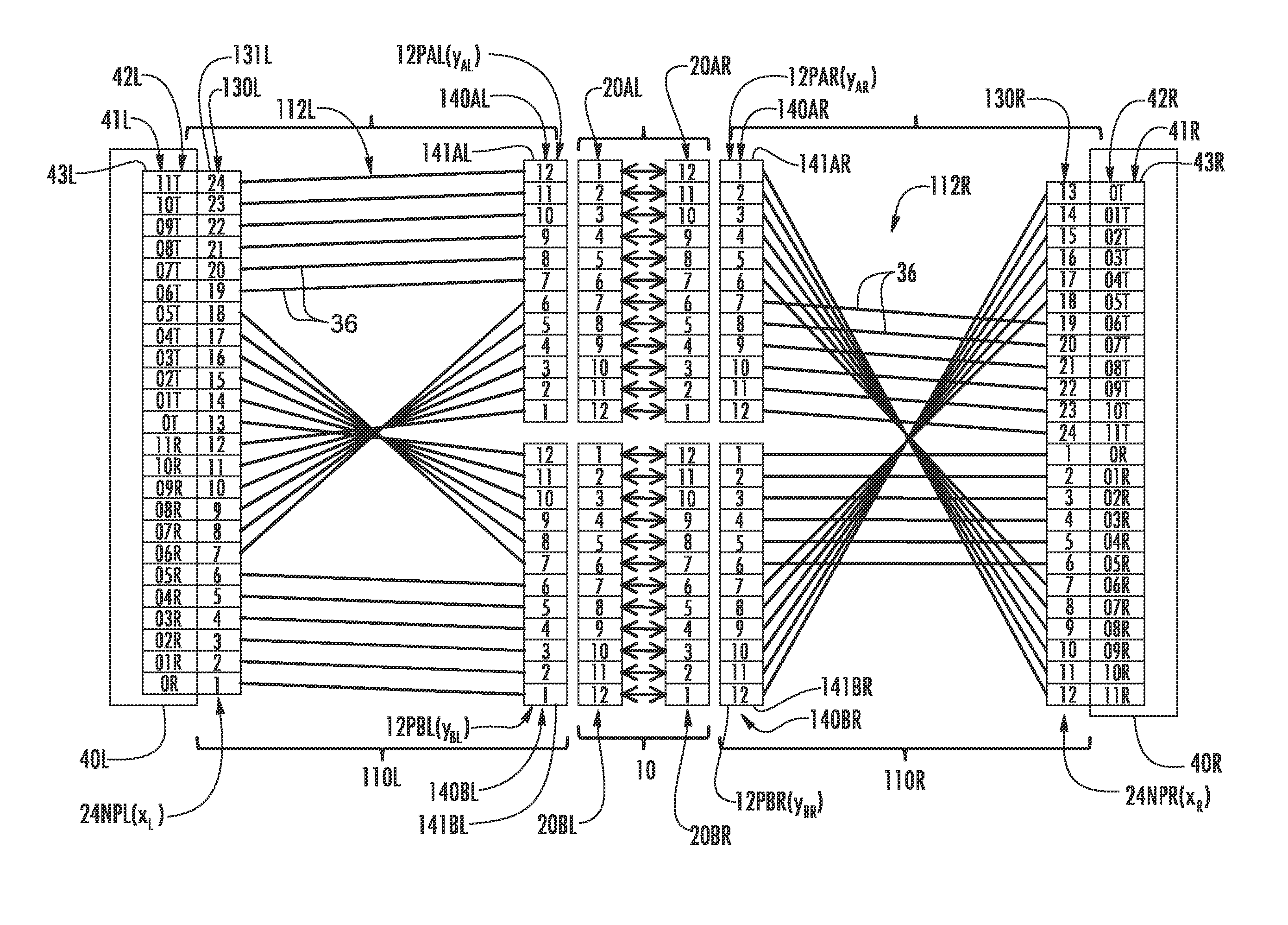
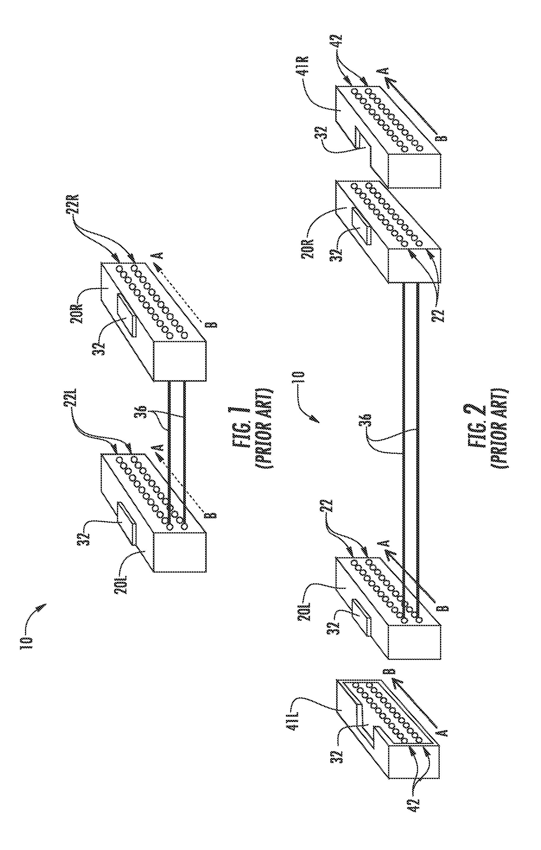
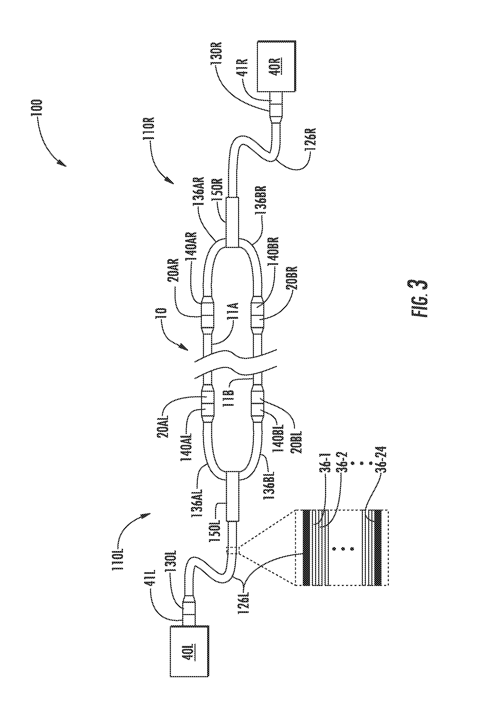
[0028]Reference is now made in detail to the embodiments of the disclosure, examples of which are illustrated in the accompanying drawings. Whenever possible, like or similar reference numerals are used throughout the drawings to refer to like or similar parts. The letters “L” and “R” in the reference numbers denote “left” and “right” to distinguish between the same or like parts in different sections of an apparatus, system, assembly or network, and are used in the same manner as “first” and “second” and thus are not intended as being limiting as to position.

[0029]It should be understood that the embodiments disclosed herein are merely examples, each incorporating certain benefits of the present disclosure. Various modifications and alterations may be made to the following examples within the scope of the present disclosure, and aspects of the different examples may be mixed in different ways to achieve yet further examples. Accordingly, the scope of the disclosure is to be underst...


PUM


Abstract

Optical interconnection methods for high-speed data-rate optical transport systems are disclosed that optically interconnect active assemblies to a fiber optic cable in a polarization-preserving manner. The methods include defining active-assembly-wise connector ports that connect to active assembly transmit and receive ports, and defining or establishing a pairings method between the active-assembly-wise connector ports. In a first optical interconnection assembly, an active-assembly-wise port is optically connected to a cable-wise port. In the second optical interconnection assembly, the cable-wise port that corresponds to the connected cable-wise port in the first optical interconnection assembly is optically connected to a select active-assembly-wise port as defined by the pairings method. The optical connection process is then repeated from the second to the first optical interconnection assembly. The optical interconnection acts are repeated until all of the active-assembly-wise ports are connected.

Description

TECHNICAL FIELD[0001]The present disclosure relates to optical fiber networks, and in particular to optical interconnection methods for high-speed data-rate optical transport systems that use multifiber connectors.BACKGROUND ART[0002]Some conventional optical fiber networking solutions for high-speed data-rate optical transport systems utilize 12-fiber (12f) connector assemblies and often have a point to point configuration. The conservation of fiber polarity (i.e., the matching of transmit and receive functions for a given fiber) is addressed by flipping fibers in one end of the assembly just before entering the connector in an epoxy plug, or by providing “A” and “B” type break-out modules where the fiber is flipped in the “B” module and “straight” in the “A” module. Polarity preserving optical interconnection assemblies that provide fiber optic interconnection solutions for multifiber connectors in a network environment are discussed in U.S. Pat. Nos. 6,758,600 and 6,869,227, whic...

Claims


Application Information

Patent Timeline
Patent Type & Authority Patents(United States)
IPC IPC(8): G02B6/00G02B6/38
CPCG02B6/0365G02B6/3502G02B6/3885G02B6/4471G02B6/3644G02B6/3668G02B6/3672G02B6/368G02B6/3825G02B6/3897
Inventor BARNES, RAY S.COLEMAN, JOHN D.UGOLINI, ALAN W.
Owner CORNING OPTICAL COMM LLC
Why Eureka
Try Eureka