Optical node for mesh-type WDM optical network

a technology of optical network and optical node, which is applied in the field of optical node, can solve the problem of inability to distinguish wavelength channels in the above manner, and achieve the effect of reducing the number of wdm optical transceivers

Inactive Publication Date: 2011-08-30
ELECTRONICS & TELECOMM RES INST
View PDF19 Cites 17 Cited by
  • Summary
  • Abstract
  • Description
  • Claims
  • Application Information

AI Technical Summary

Benefits of technology

[0017]The present invention provides an optical node capable of supporting a mesh-type network, which can support input and output of an optical fiber in various directions and remarkably reduce the number of WDM optical transceiver.
[0022]In addition, the electrical cross connect switch may drop all the electrical signals in the specific wavelength channel toward the external client and outputs to the optical transceiver all the signals added by the external client with a unit of a wavelength channel.

Problems solved by technology

However, when the optical network has a large scale, and traffic increases, it is impossible to distinguish the wavelength channels in the aforementioned manner.

Method used


Image

  • Optical node for mesh-type WDM optical network
  • Optical node for mesh-type WDM optical network
  • Optical node for mesh-type WDM optical network

Examples


Embodiment Construction

[0031]Hereinafter, preferred embodiments of the present invention will be described in detail with reference to the attached drawings. Like reference numerals in the drawings denote like elements. When it is determined that the detailed descriptions of known techniques or structures related to the present invention depart from the scope of the invention, the detailed descriptions will be omitted.

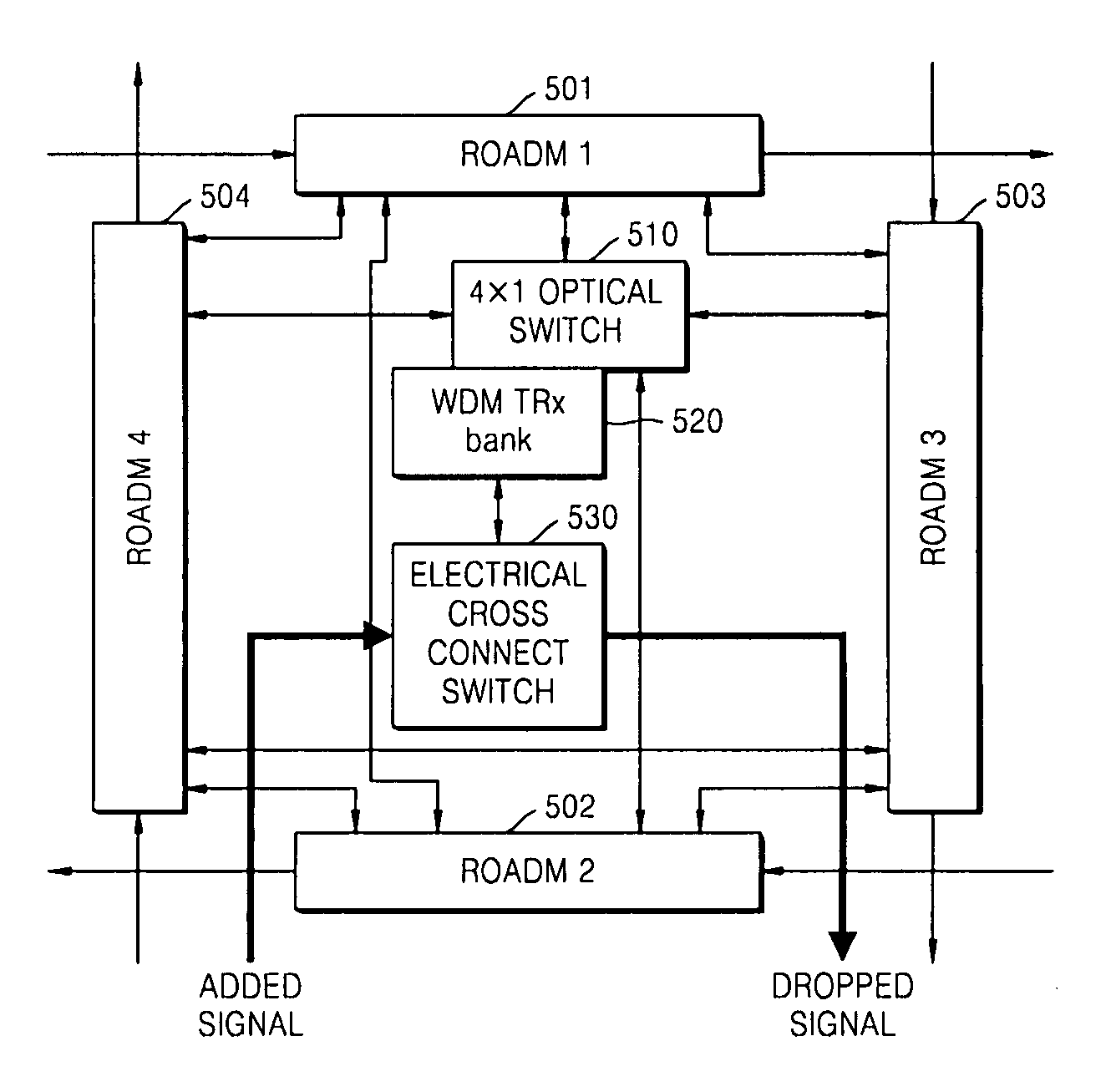
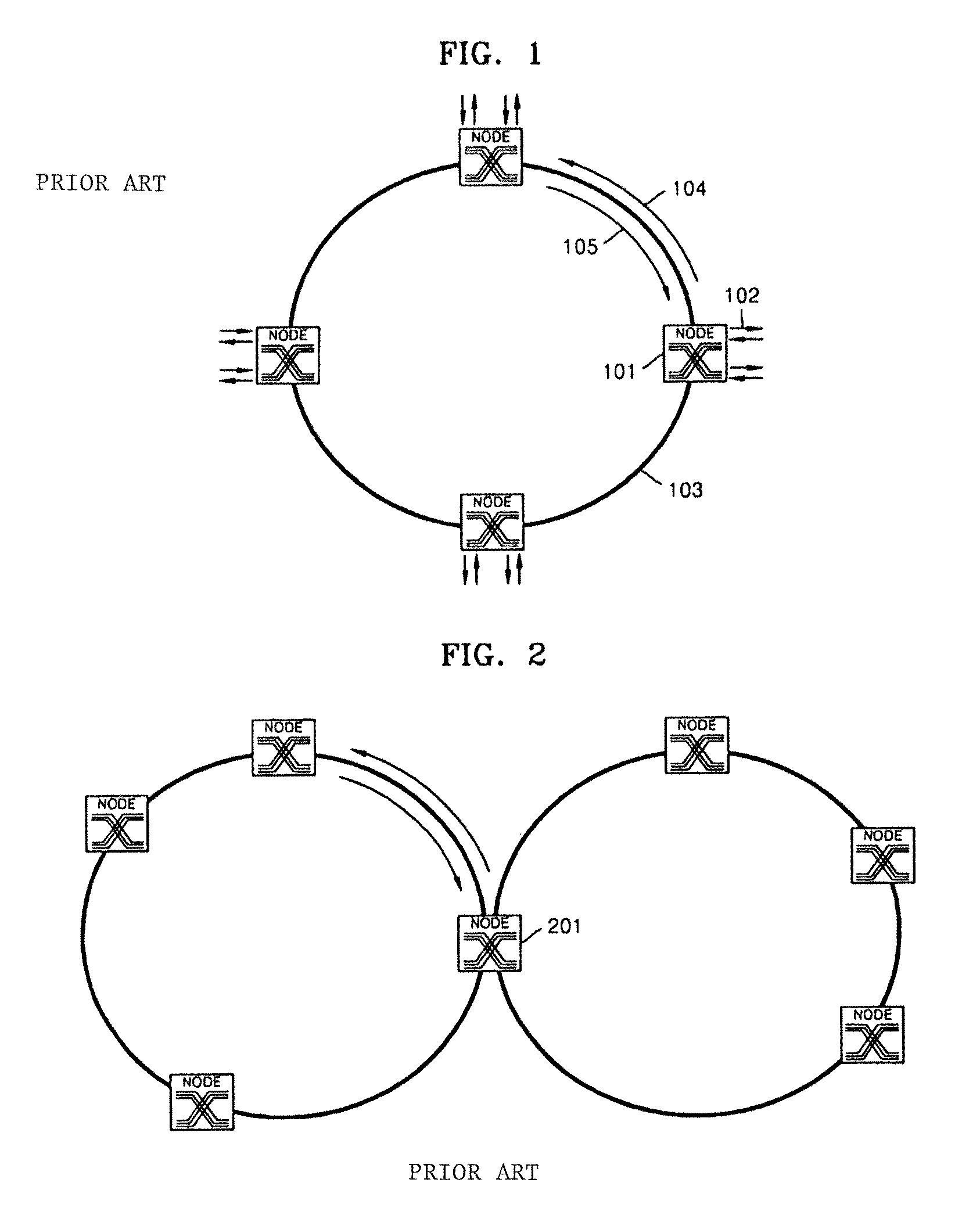
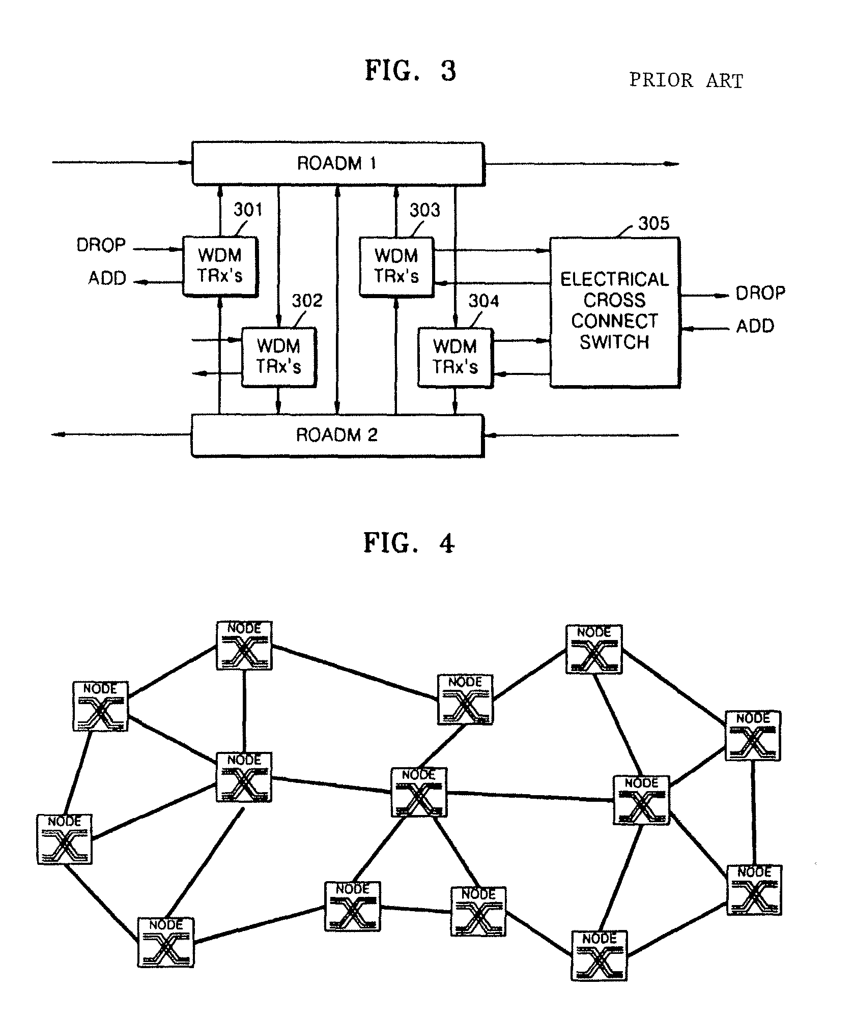
[0032]FIG. 4 is a schematic diagram illustrating a mesh-type optical network according to an embodiment of the present invention. Since the network may include 2 to 8 or more inputs and outputs, the structure of the node may be complicated. Accordingly, in the present invention, there is provided a node structure capable of supporting a mesh-type network, which has an economical advantage since the mesh-type network can support optical fiber inputs and outputs from various directions and remarkably reduce the number of the WDM optical transceiver TRxs.

[0033]FIG. 5 illustrates a structure of ...


PUM


Abstract

An optical node capable of supporting a mesh-type optical network is provided. The node includes: N ROADMs, which separate specific wavelength channels from a multiple wavelength channel optical signal that is input from any node constituting the optical network, allows the rest of the wavelength channels to be passed, and combine another added wavelength channel with the passed wavelength channel to allow the combined wavelength channel to be passed; an N×1 optical switch which selects the specific wavelength channel separated from one of the N ROADMs and inputs the specific wavelength channel into an optical transceiver and selects one of the N ROADMs and connects a wavelength channel that is output from the optical transceiver to the selected ROADM; and an electrical cross connect switch which drops a part of electrical signal bandwidth of the specific wavelength channels separated by the ROADM, which is converted into the electrical signals in the optical transceiver, toward an external client and combines the rest of the electrical signal bandwidth with a electrical signal added by the external client to form an electrical signal bandwidth of a wavelength channel and output the electrical signal to the optical transceiver. Accordingly, optical fiber inputs and outputs in various directions can be supported, and the number of WDM transceivers used for each node is remarkably reduced, thereby improving efficiency and economical efficiency of a network.

Description

CROSS-REFERENCE TO RELATED PATENT APPLICATION[0001]This application claims the benefit of Korean Patent Application No. 10-2006-0114095, filed on Nov. 17, 2006, in the Korean Intellectual Property Office, the disclosure of which is incorporated herein in its entirety by reference.BACKGROUND OF THE INVENTION[0002]1. Field of the Invention[0003]The present invention relates to a node structure capable of supporting a mesh-type optical network, and more particularly, to an optical node capable of supporting a mesh-type optical network in a wavelength division multiplexing (WDM) optical transmission system.[0004]2. Description of the Related Art[0005]As demand for large transmission capacities has rapidly increased, a wavelength division multiplexing (WDM) optical transmission system has been developed. The WDM optical system is considered as a solution for satisfying this demand. In the WDM optical transmission technique, a plurality of wavelength channels are concurrently transmitted ...

Claims


Application Information

Patent Timeline
Patent Type & Authority Patents(United States)
IPC IPC(8): H04J14/02H04B10/2581
CPCH04J14/021H04J14/0206H04J14/0212H04J14/0217H04B10/00H04B10/2581H04B10/27
Inventor CHANG, SUN HYOKCHUNG, HWAN SEOKLEE, SANG SOOKIM, KWANGJOON
Owner ELECTRONICS & TELECOMM RES INST
Why Eureka
Try Eureka