Resonant stator balancing of free piston machine coupled to linear motor or alternator

a free-piston stirling cycle, linear motor technology, applied in the direction of dynamo-electric machines, electrical apparatus, control systems, etc., can solve the problems of increasing the weight and increasing the cost and volume of combined and linked stirling machines. , to achieve the effect of reducing vibration, minimizing or eliminating vibration

Active Publication Date: 2011-09-06
GLOBAL COOLING
View PDF3 Cites 23 Cited by
  • Summary
  • Abstract
  • Description
  • Claims
  • Application Information

AI Technical Summary

Benefits of technology

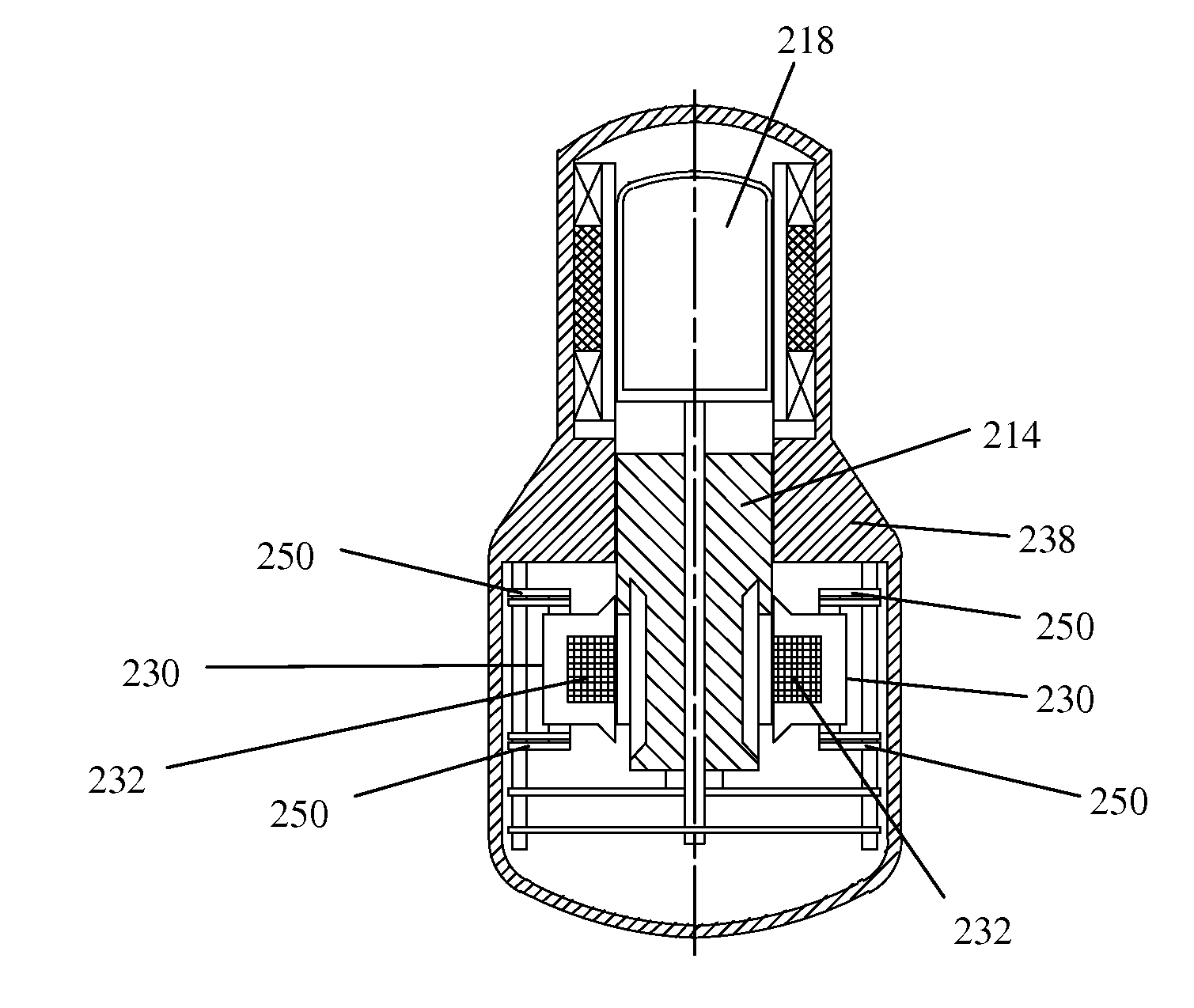
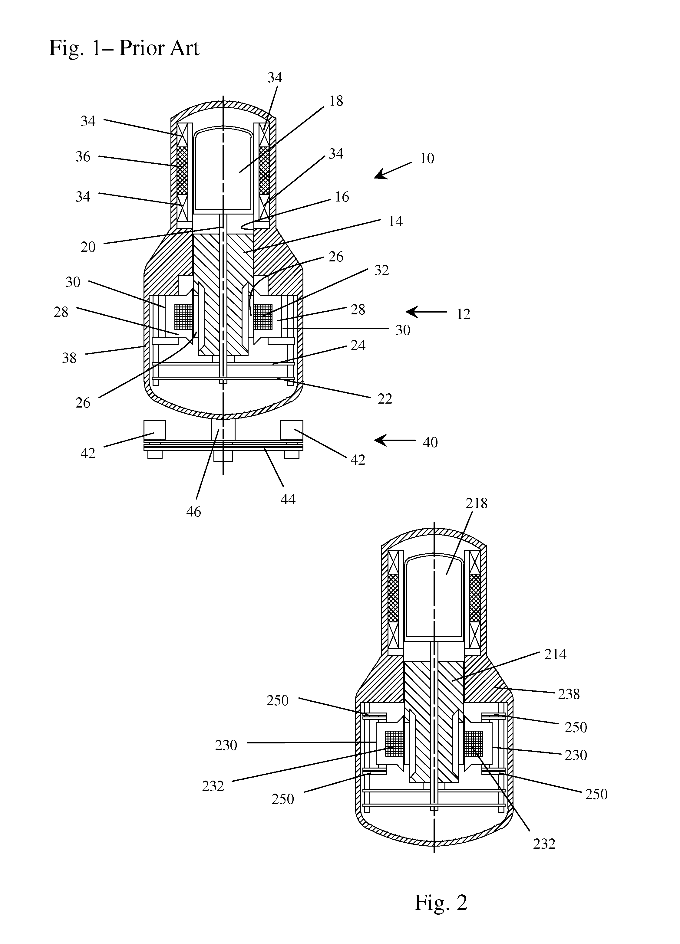
[0018]The invention eliminates the need for the passive vibration balancing unit. Instead of mounting the stator of the linear electro-magnetic-mechanical transducer in rigid connection to the interior of the casing, the stator is mounted through one or more springs to the interior of the casing so that it is free to move on the springs. The springs are arranged to permit the stator to reciprocate along the axis of reciprocation of the other reciprocating parts and flex the springs during operation of the Stirling machine and coupled transducer. The stator, the displacer and the piston are each a mass having spring forces acting upon them and therefore each has a resonant frequency. Vibration is reduced, minimized or eliminated by designing the coupled masses of the machines to have substantially or approximately the particular mathematical relationships between these resonant frequencies, the operating frequency and the damping, spring coupling and other parameters of the coupled machines, as explained in the detailed description. Generally, the stator resonant frequency should be substantially or essentially equal to the operating frequency of the coupled Stirling machine and the linear electro-magnetic-mechanical transducer and slightly below the piston resonant frequency.
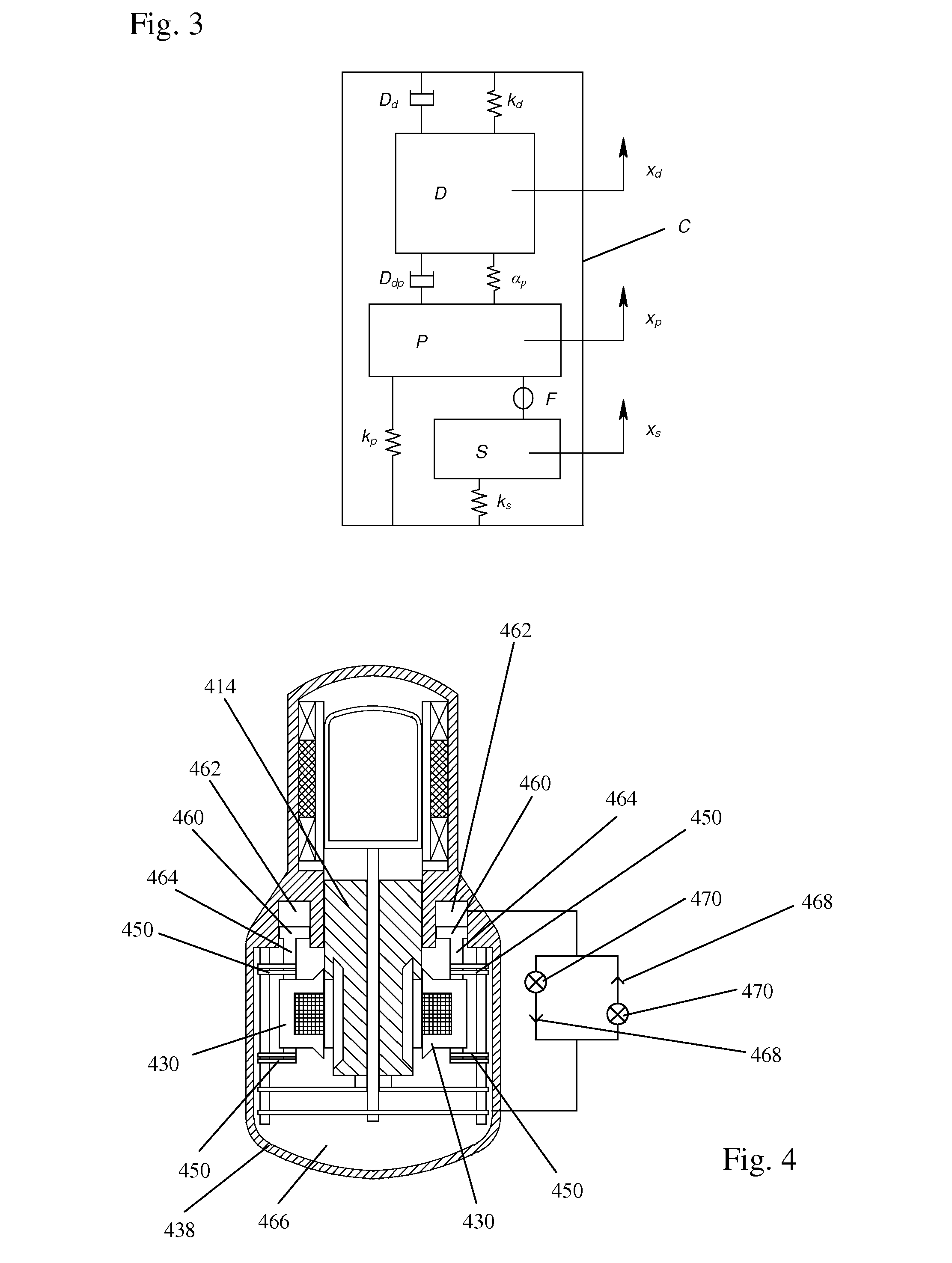
[0019]However, in some implementations of a Stirling machine coupled to a linear electro-magnetic-mechanical transducer, the piston resonant frequency changes as a function of temperature and mean working gas pressure. Therefore, for those machines in which the temperature and / or mean pressure may vary during the course of operation, the changes in temperature or mean pressure are compensated for by structures that vary the spring coupling between the stator and the casing or between the piston and the casing. Varying the spring coupling shifts the resonant frequency of the stator or the piston to maintain the mathematical relationships of the parameters that minimize the vibrations and thereby compensates for the changes.

Problems solved by technology

The reciprocating motion of these parts causes oscillating forces to be applied to the casing which results in vibration of the casing and any object to which the casing is mounted.
The vibration balancer, most typically a passive vibration balancer, increases the cost and volume of, and adds substantial weight to, the combined and linked Stirling machine and linear electro-magnetic-mechanical transducer.
The vibration balancer typically must be tuned with very high precision to the actual operating frequency and this is often difficult.
Additionally, the effectiveness of the vibration balancer deteriorates if the operating frequency of the coupled Stirling machine and linear alternator or motor drifts away from the resonant frequency to which the vibration balancer is tuned.
A vibration balancer can also cause unwanted dynamic behavior of a Stirling cooler by causing the cooler to have an engine mode operating in conjunction with the normal cooling mode resulting from the generation of beat frequencies.

Method used


Image

  • Resonant stator balancing of free piston machine coupled to linear motor or alternator
  • Resonant stator balancing of free piston machine coupled to linear motor or alternator
  • Resonant stator balancing of free piston machine coupled to linear motor or alternator

Examples


Embodiment Construction

[0029]Basic Vibration Balancing

[0030]FIG. 2 illustrates the basic invention. The components illustrated in FIG. 2 are like those in FIG. 1 except as described or obvious to a person skilled in the art from this description. In the embodiment of FIG. 2, the stator 230 is mounted to the interior of the casing 238 through interposed springs 250. This permits the stator to reciprocate and flex the springs 250 during operation of the Stirling machine and coupled linear motor or alternator. The stator itself becomes an oscillating mass that reciprocates along the axis of reciprocation that is common to the power piston 214 and the displacer 218 including the masses that are attached to and reciprocate respectively with each. Although FIG. 2 illustrates the use of mechanical springs for connecting the stator 230 to the casing 238, other types of springs may also be used as previously described. As a result, the stator 230 simultaneously serves both as the stator of a linear motor or altern...


PUM


Abstract

A beta-type free-piston Stirling cycle engine or cooler is drivingly coupled to a linear alternator or linear motor and has an improved balancing system to minimize vibration without the need for a separate vibration balancing unit. The stator of the linear motor or alternator is mounted to the interior of the casing through an interposed spring to provide an oscillating system permitting the stator to reciprocate and flex the spring during operation of the Stirling machine and coupled transducer. The natural frequency of oscillation, ωs, of the stator is maintained essentially equal toωp⁢1-αpkpand the natural frequency of oscillation of the piston, ωp, is maintained essentially equal to the operating frequency, ωo of the coupled Stirling machine and alternator or motor. For applications in which variations of the average temperature and / or the average pressure of the working gas cause more than insubstantial variations of the piston resonant frequency ωp, various alternative means for compensating for those changes in order to maintain vibration balancing are also disclosed.

Description

CROSS-REFERENCES TO RELATED APPLICATIONS[0001]This application claims the benefit of U.S. Provisional Application No. 60 / 954,824 filed Aug. 9, 2007.STATEMENT REGARDING FEDERALLY-SPONSORED RESEARCH AND DEVELOPMENT[0002](Not Applicable)REFERENCE TO AN APPENDIX[0003](not Applicable)BACKGROUND OF THE INVENTION[0004]1. Field of the Invention[0005]This invention relates generally to beta-type free-piston Stirling cycle engines and coolers coupled to a linear alternator or linear motor and more particularly relates to balancing such a coupled system to minimize vibration without the need for a passive vibration balancing unit as is conventionally used.[0006]2. Description of the Related Art[0007]Stirling cycle engines are recognized as efficient thermo-mechanical devices for transducing heat energy to mechanical energy for driving a mechanical load. Similarly, Stirling cycle coolers are recognized as being efficient for transducing mechanical energy to the pumping of heat energy from a coo...

Claims


Application Information

Patent Timeline
Patent Type & Authority Patents(United States)
IPC IPC(8): F01B29/10H02P9/04
CPCF02G1/043F02G1/053F02G2275/10F02G2280/10F02G1/0435
Inventor BERCHOWITZ, DAVID M.
Owner GLOBAL COOLING
Why Eureka
Try Eureka