Endoscope device and control method for the same

a technology of endoscope and control method, which is applied in the field of endoscope device and control method for the same, can solve the problems of difficult insertion to a deep portion, difficult to transmit the pushing force to the distal end, and become impossible to insert the insertion portion to a deeper side, so as to prevent the body from pressing the cavity

Active Publication Date: 2011-09-06
FUJI PHOTO OPTICAL CO LTD
View PDF33 Cites 40 Cited by
  • Summary
  • Abstract
  • Description
  • Claims
  • Application Information

AI Technical Summary

Benefits of technology

[0007]The invention was made in view of these circumstances, and an object thereof is to provide an endoscope device and a control method for the same which can reduce the burden on the body cavity from balloons.
[0009]According to the first aspect of the invention, since the first balloon and the second balloon have the same friction resistance against the body cavity when they are expanded, when both balloons are expanded and the insertion portion and the insertion guide are pushed or pulled, the balloons can be prevented from pressurizing the body cavity. In addition, both balloons can be set to have a friction resistance that makes the balloons least likely to damage the body cavity and to be securely fixed in the body cavity.
[0014]According to the fifth aspect of the invention, the first balloon and the second balloon becomes equal to each other in friction resistance against the body cavity when they are expanded, so that when the balloons are expanded and the insertion portion and the insertion guide are pushed or pulled, the balloons can be prevented from pressurizing the body cavity. In addition, the balloons can be set to have a friction resistance that makes the balloons least likely to damage the body cavity and to be securely fixed in the body cavity.

Problems solved by technology

When an insertion portion of an endoscope is inserted in a deep digestive tract such as the small intestine, if the insertion portion is only pushed and inserted, it is difficult to transmit the pushing force to the distal end of the insertion portion due to complicated bends of the intestinal tract, and insertion to a deep portion is difficult.
For example, when the insertion portion unnecessarily bends or warps, it becomes impossible to insert the insertion portion to a deeper side.
However, the endoscope devices of JP-A-51-11689 and JP-A-11-290263 have a possibility that when the two balloons are expanded and the insertion portion and the insertion guide are pushed or pulled, the balloons pressurize the intestinal wall and impose a heavy burden on the intestinal tract.

Method used


Image

  • Endoscope device and control method for the same
  • Endoscope device and control method for the same
  • Endoscope device and control method for the same

Examples


Embodiment Construction

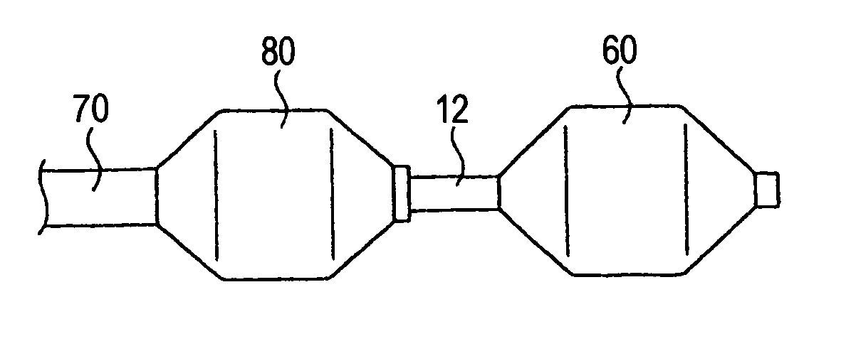
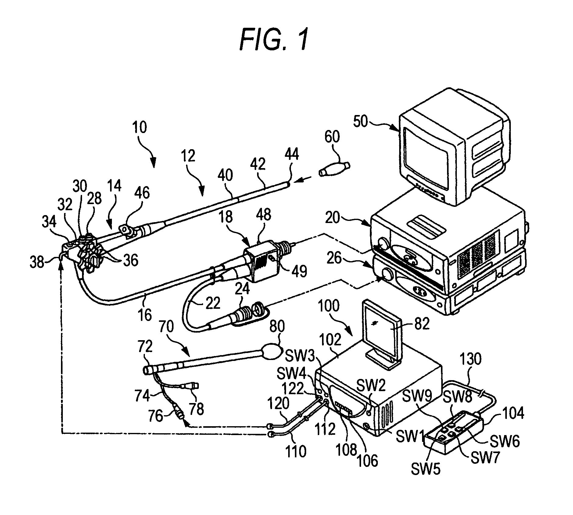
[0020]Hereinafter, an endoscope device and a control method for the same according to the invention are described in detail with reference to the accompanying drawings. FIG. 1 is a system constructional diagram of an embodiment of an endoscope device according to the invention. As shown in FIG. 1, the endoscope device mainly comprises an endoscope 10, an insertion guide 70, and a balloon controller 100.

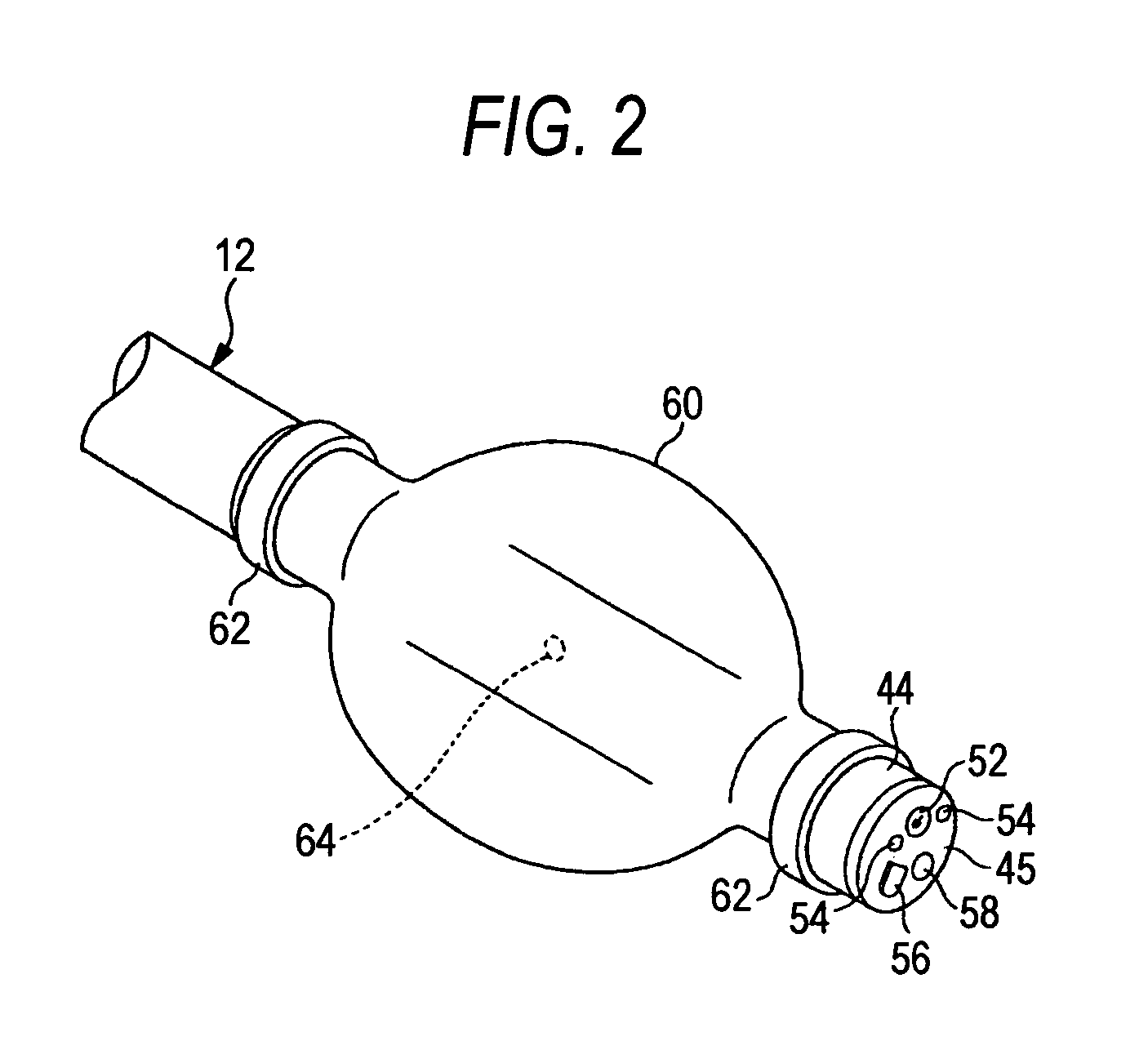
[0021]As shown in FIG. 1, the endoscope 10 has a hand-side control portion 14, and an insertion portion 12 that is continued from the hand-side control portion 14 and is to be inserted into a body cavity. To the hand-side control portion 14, a universal cable 16 is connected, and on the distal end of this universal cable 16, an LG connector 18 is provided. The LG connector 18 is detachably linked to a light source device 20, whereby illumination light is supplied to an illumination optical system 54 (see FIG. 2) described later. In addition, to the LG connector 18, an electrical conne...


PUM


Abstract

An endoscope device comprises: an endoscope including an insertion portion and a first balloon attached to a distal end of the insertion portion; and an insertion guide that is to be covered on the insertion portion to guide insertion of the insertion portion, the insertion guide comprising a second balloon on its distal end, wherein the insertion portion or the insertion guide is fixed in a body cavity by expanding the first balloon or the second balloon, respectively, wherein the first balloon and the second balloon are substantially equal to each other in friction resistance against the body cavity when they are expanded.

Description

BACKGROUND OF THE INVENTION[0001]1. Field of the Invention[0002]The present invention relates to an endoscope device and a control method for the same, and more specifically, an endoscope device to be used for observation of deep digestive tracts such as the small intestine and the colon, and a control method for the same.[0003]2. Description of the Related Art[0004]When an insertion portion of an endoscope is inserted in a deep digestive tract such as the small intestine, if the insertion portion is only pushed and inserted, it is difficult to transmit the pushing force to the distal end of the insertion portion due to complicated bends of the intestinal tract, and insertion to a deep portion is difficult. For example, when the insertion portion unnecessarily bends or warps, it becomes impossible to insert the insertion portion to a deeper side. Therefore, a method for preventing unnecessary bending and warping of the insertion portion of an endoscope by guiding the insertion porti...

Claims


Application Information

Patent Timeline
Patent Type & Authority Patents(United States)
IPC IPC(8): A61B1/00A61F2/958
CPCA61B1/00082A61B1/00091A61B1/00154A61B1/01A61B17/12045A61B17/12136A61B2017/12127A61B2017/22054A61B2017/22065A61B1/12
Inventor MACHIDA, MITSUNORI
Owner FUJI PHOTO OPTICAL CO LTD
Why Eureka
Try Eureka