Front loaded medical fluid syringe mounting

Inactive Publication Date: 2011-09-06
LIEBEL FLARSHEIM CO
View PDF12 Cites 16 Cited by
  • Summary
  • Abstract
  • Description
  • Claims
  • Application Information

AI Technical Summary

Benefits of technology

[0016]In accordance with another aspect of the present invention, leakage is prevented by including a non-planar sealing flange on the syringe, positioned on the syringe forward of the locking structure. In specific embodiments of this aspect, the non-planar sealing flange includes a cusp feature for diverting fluid flowing along the surface of the syringe.
[0017]In yet another aspect of the present invention, leakage is prevented by a two-piece structure, including a syringe and a separate leakage stopping washer for surrounding the syringe to halt the flow of fluid along the exterior of the syringe.
[0018]A separate unique feature of this aspect of the invention, is the structure of the syringe, which includes an annul

Problems solved by technology

There are several disadvantages to including an annular disc-like sealing flange on the syringe.
This disc-like flange can be difficult to mold, and w

Method used


Image

  • Front loaded medical fluid syringe mounting
  • Front loaded medical fluid syringe mounting
  • Front loaded medical fluid syringe mounting

Examples


Example

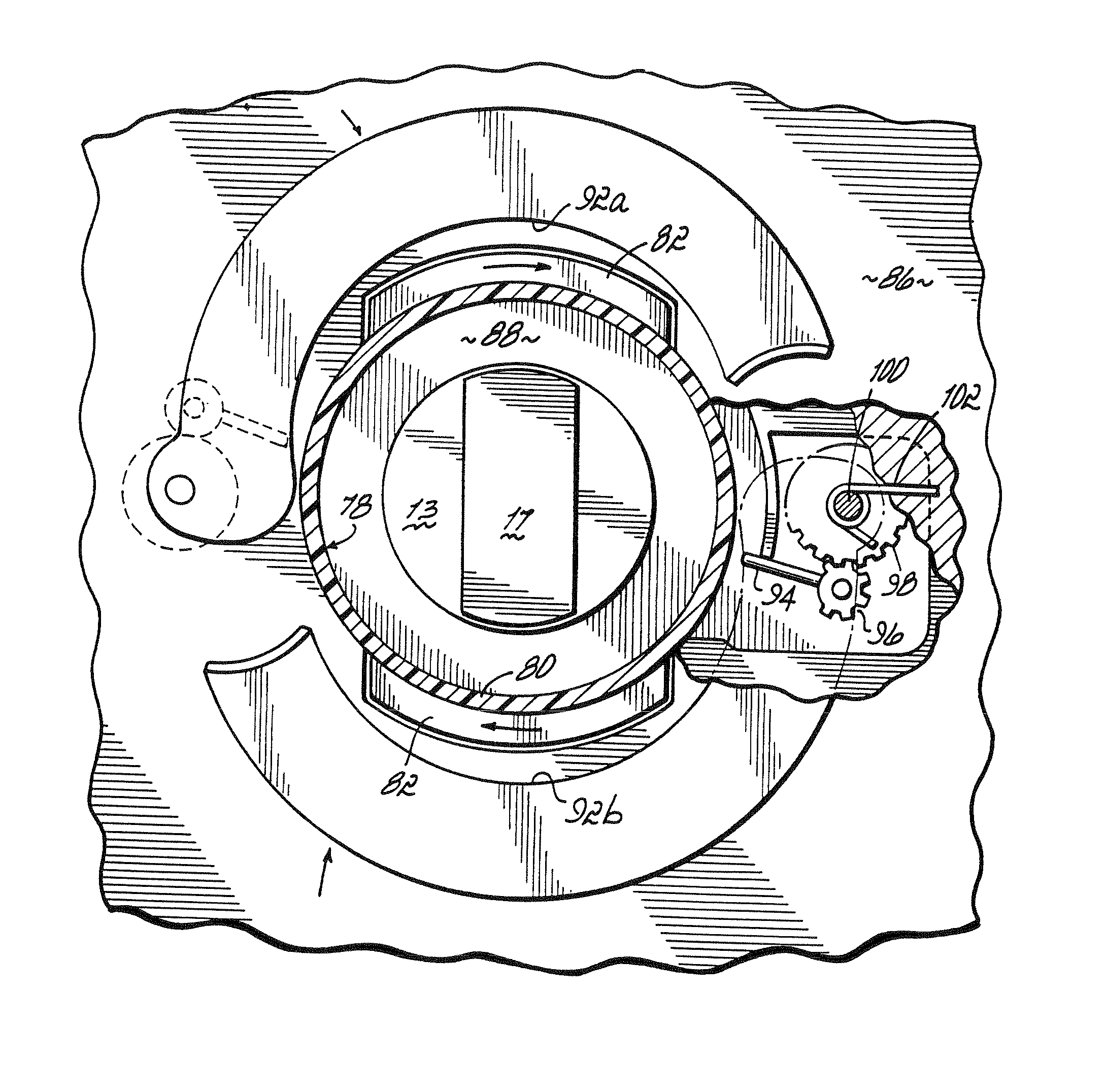
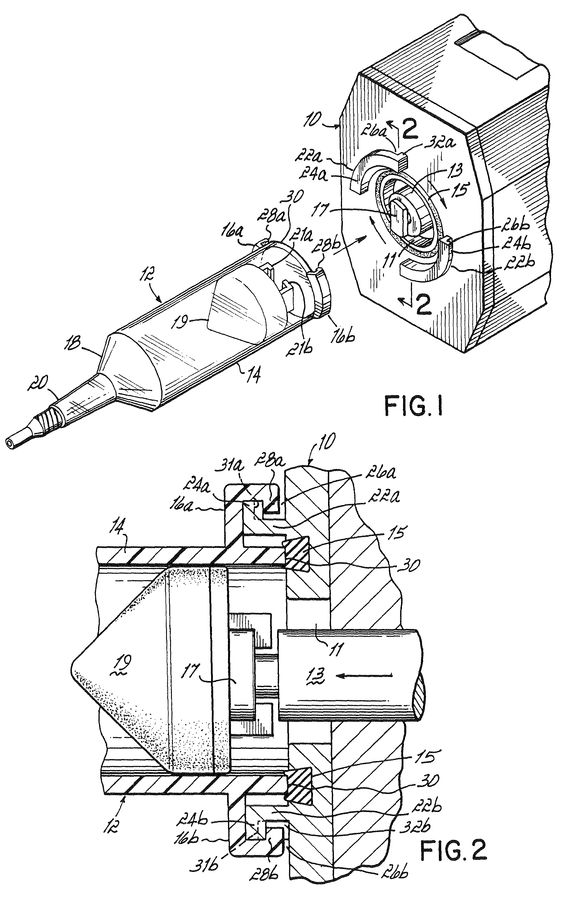
[0035]Referring now to FIG. 1, in accordance with a first embodiment of the present invention, the injector disclosed in U.S. Pat. No. 5,383,858 is outfitted with a replacement face plate 10, incorporating features for mounting a syringe 12. Face plate 10 includes an opening 11 at a central location thereof. The syringe drive ram 13 of the injector extends through opening 11 to engage the plunger of a syringe mounted to face plate 10, by a relative rotational motion of the plunger and ram, in the manner described in U.S. Pat. No. 5,383,858. Surrounding opening 11 is a circular gasket 15 of a flexible material such as rubber.

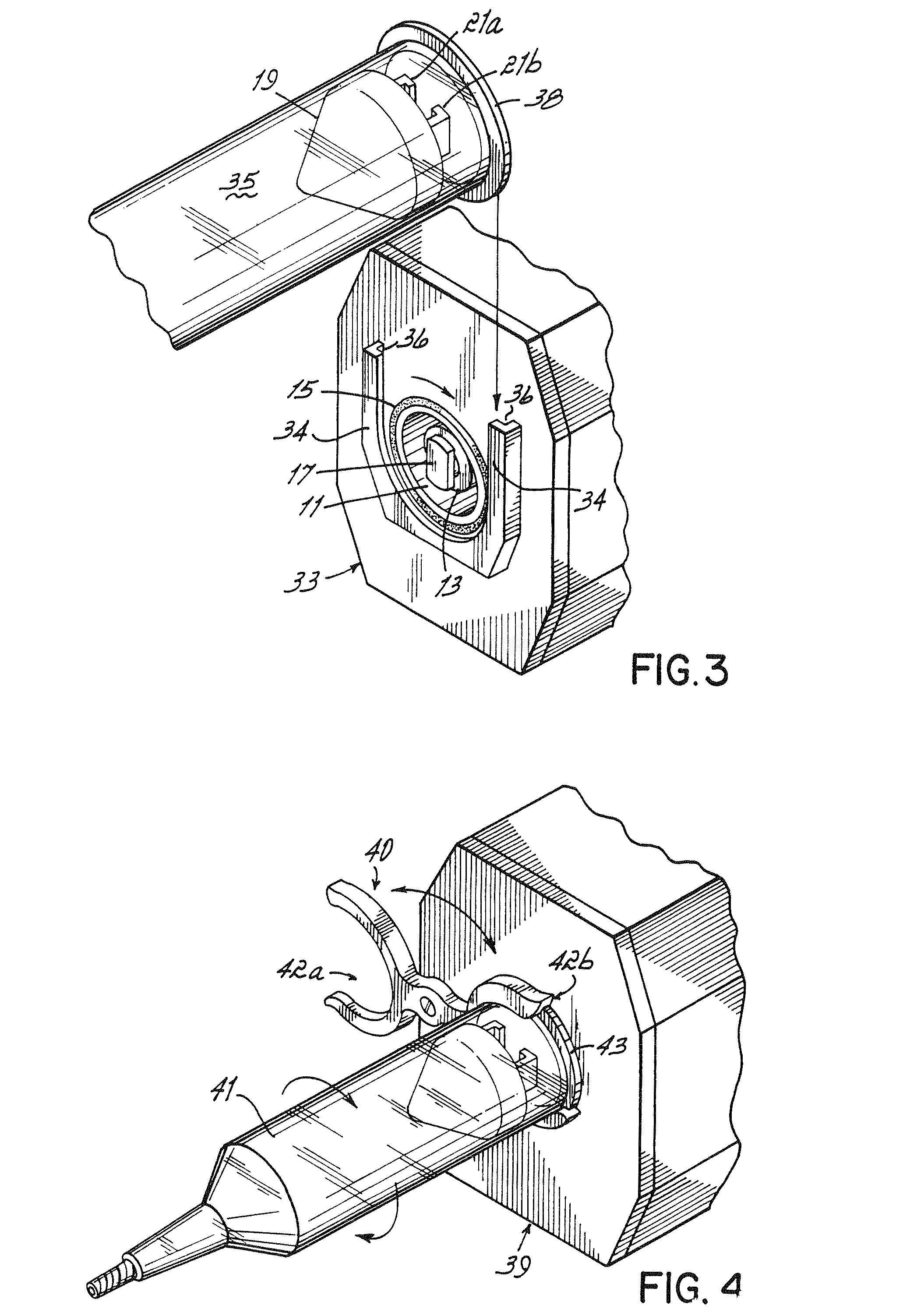
[0036]The structure of syringe 12 is notable in that it does not include a disc-like sealing flange on its exterior. Rather, the exterior surface of cylindrical barrel 14 of the syringe is smooth but for two locking flanges 16a and 16b extending from the rearward end of the syringe. The syringe also includes, as is conventional, a plunger 19 sealingly engaging an...


PUM


Abstract

Various sealing structures are used in a front-loading injector, for preventing leakage of spilled fluid from an external surface of a syringe into the vicinity of the drive ram. For example, a sealing gasket may be incorporated into the front face of the injector housing, for mating to the rearward circular edge of the cylindrical body of a syringe. Alternatively, sealing and locking functions may be performed by a single structure on the rearward end of the syringe. Further, leakage may be prevented by including a non-planar sealing flange on the syringe, positioned on the syringe forward of the locking structure, or by a two-piece structure, including a syringe and a separate leakage stopping washer for surrounding the syringe to halt the flow of fluid along the exterior of the syringe. As part of this aspect, or as an independent feature, the syringe may include an annularly discontinuous flange forward of the locking structure, for providing mechanical support for the syringe against the injector. Alternatively, an iris-like structure may be incorporated into the front surface of the injector, for closing about the syringe upon insertion of the syringe into the injector.

Description

CROSS REFERENCE TO RELATED APPLICATIONS[0001]This application is a division of U.S. patent application Ser. No. 10 / 386,957 filed 12 Mar. 2003, which is a division of U.S. Pat. No. 6,569,127, filed 20 Sep. 2000, which is a continuation of now abandoned U.S. patent application Ser. No. 08 / 896,695 filed 18 Jul. 1997, the entire disclosures of which are hereby incorporated by reference.[0002]Further, this application is related to U.S. patent application Ser. No. 11 / 458,463 filed 19 Jul. 2006, and co-pending U.S. patent application Ser. No. 11 / 420,664 filed 26 May 2006, which claims the same priority as above.[0003]Further, this application is related to U.S. patent application Ser. No. 11 / 677,946 filed 22 Feb. 2007, and U.S. patent application Ser. No. 11 / 677,926, filed 22 Feb. 2007, which claims the same priority as above.[0004]Further, this application is related to U.S. patent application Ser. No. 11 / 738,925, filed Apr. 23, 2007, which claims the same priority as above.FIELD OF THE ...

Claims


Application Information

Patent Timeline
IPC IPC(8): A61M1/00A61M5/145
CPCA61M5/14546A61M5/14566
Inventor FAGO, FRANK M.ZIEMBA, ROBERTWAGNER, GARY S.
Owner LIEBEL FLARSHEIM CO
Why Eureka
Try Eureka