

Image forming optical system and electronic image pickup apparatus equipped with same
a technology of which is applied in the field of image forming optical system and electronic image pickup apparatus equipped with same, can solve the problems of large negative spherical aberration of g-line and h-line, large first lens group, and difficult to ensure the bending of the beam needed for imaging at all the angle of view, etc., to achieve high optical specifications, short overall length, and low depth
- Summary
- Abstract
- Description
- Claims
- Application Information
AI Technical Summary
Benefits of technology
Problems solved by technology
Method used
Image

Examples
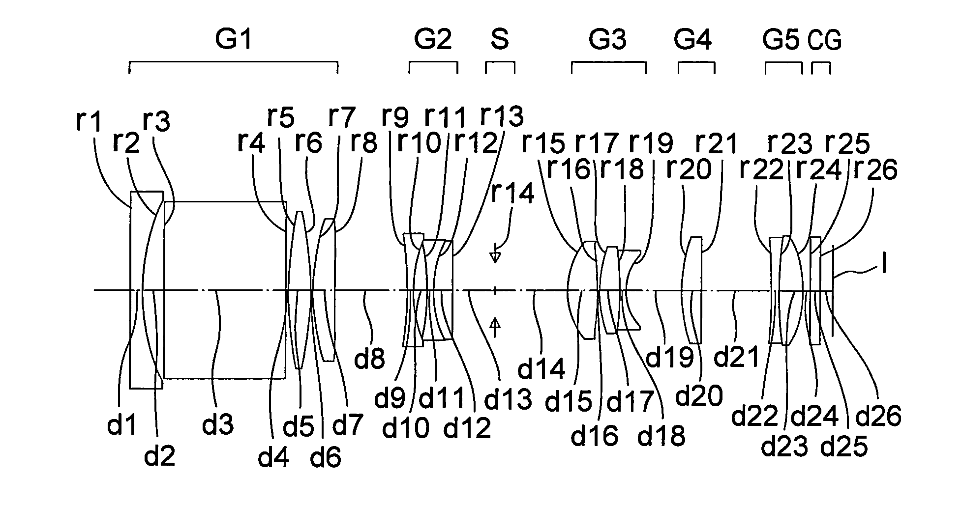
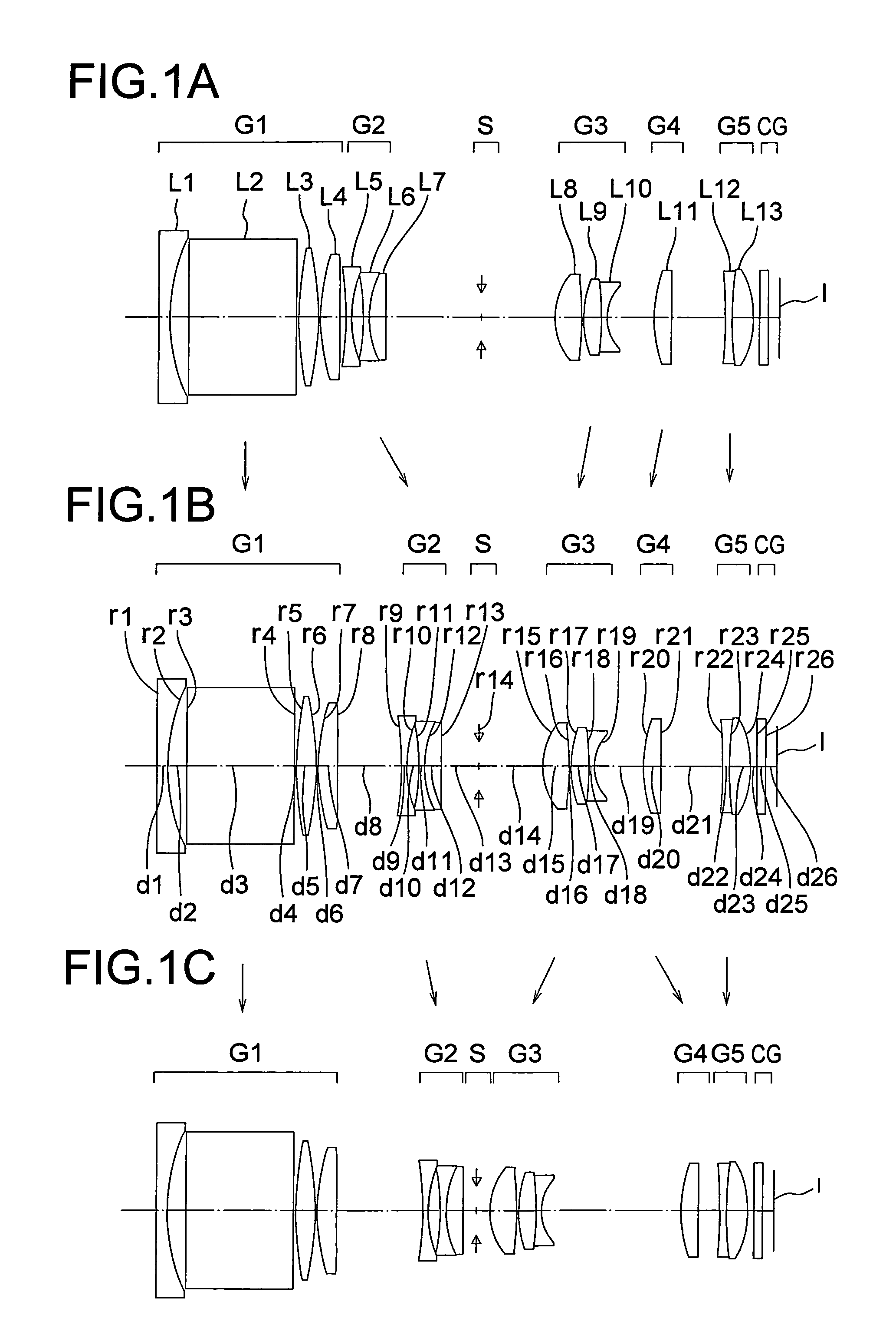
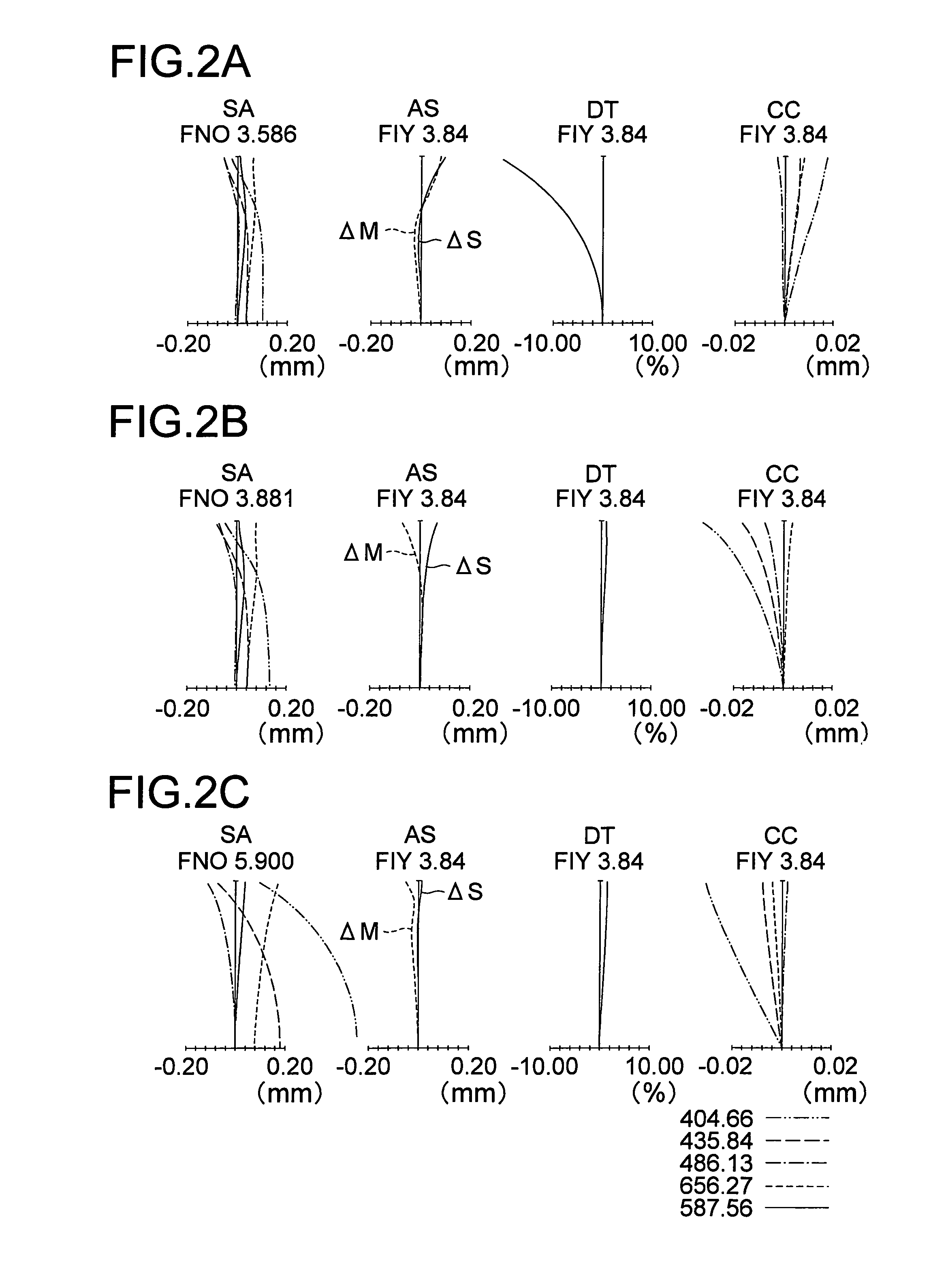
numerical example 1
Unit mm
[0667]
Surface dataSurfacenumberrdndνdObject plane∞∞ 1∞1.00002.1435217.77 217.77071.7000 3∞9.80002.1435217.77 4∞0.2000 5*36.79771.80001.7432049.34 6−26.11390.1500 718.05241.80001.8061040.92 8−225.8693Variable 9−26.03810.50001.8348142.7110*12.32971.100011−15.81990.50001.8061040.92129.19541.50001.9459517.9813175.4980Variable14(STOP)∞Variable15*6.29832.50001.8348142.7116*−20.97690.15001711.80571.60001.6968055.5318−25.49960.50002.0006925.46194.4488Variable20*13.74041.60001.5254056.2521−285.2486Variable22*−36.63270.60002.1435217.772342.87392.00001.5163364.1424−9.19310.600025∞0.80001.5163364.1426∞0.9996Image plane∞
Aspheric Surface Data
5th Surface[0668]K=−0.3283,[0669]A2=0.0000E+00,A4=−4.4000E−06,A6=6.0678E−08,A8=−8.9615E−10,[0670]A10=0.0000E+00
10th Surface[0671]K=−0.8898,[0672]A2=0.0000E+00,A4=−9.6527E−06,A6=5.4330E−06,A8=−8.3037E−08,[0673]A10=0.0000E+00
15th Surface[0674]K=−0.5934,[0675]A2=0.0000E+00,A4=−5.4855E−05,A6=4.0626E−06,A8=3.1128E−07,[0676]A10=0.0000E+00
16th Surface[0677]K=...
numerical example 2
Unit mm
[0689]
Surface dataSurfaceUumberrdndνdObject plane∞∞ 1*−22.32389.80002.1435217.77 2∞0.2000 334.37071.80001.7432049.34 4−27.66000.1500 5*16.24551.80001.8061040.92 6443.7227Variable 7−36.47690.50001.8348142.71 8*8.80331.1000 9−13.35080.50001.7432049.34109.63751.50001.9459517.9811218.5437Variable12(STOP)∞Variable13*5.41392.50001.8348142.7114*−13.44400.15001513.35781.60001.6968055.5316−9.40780.50002.0006925.46173.7083Variable18*20.25131.60001.5254056.2519−35.3212Variable2055.80490.60002.0006925.462114.78952.00001.5163364.1422−10.27550.600023∞0.80001.5163364.1424∞0.5012Image plane∞
Aspherical Surface Data
1st Surface[0690]K=−0.0410,[0691]A2=0.0000E+00,A4=9.1093E−05,A6=−8.5914E−07,A8=4.4127E−09,[0692]A10=0.0000E+00
5th Surface[0693]K=−0.0773,[0694]A2=0.0000E+00,A4=−9.7118E−05,A6=2.4199E−07,A8=−4.5197E−09,[0695]A10=0.0000E+00
8th Surface[0696]K=−0.8913,[0697]A2=0.0000E+00,A4=−2.9868E−04,A6=4.4157E−05,A8=−1.4936E−06,[0698]A10=0.0000E+00
13th Surface[0699]K=−0.5894,[0700]A2=0.0000E+00,A4=−1...
numerical example 3
Unit mm
[0711]
Surface dataSurfacenumberrdndνdObject plane∞∞ 126.48221.00001.9459517.98 210.71723.3000 3∞11.5000 1.7725049.60 4−41.19070.2000 5*21.95442.80001.7432049.34 6−33.1000Variable 765.54770.50001.8348142.71 8*11.13631.5000 9−13.58080.50001.8061040.921014.96401.70001.9459517.9811−189.2732Variable12(STOP)∞Variable13*7.73572.50001.8348142.7114*−31.04880.15001511.36421.36251.6968055.5316−469.23040.50002.0006925.46175.9089Variable18*11.37701.60001.5254056.251935.1726Variable20*−16.11630.60002.1435217.772162.34032.00001.5163364.1422−8.46871.000023∞0.86751.5163364.1424∞1.2996Image plane∞
Aspherical Surface Data
5th Surface[0712]K=0.0593,[0713]A2=0.0000E+00,A4=8.2003E−06,A6=1.6810E−08,A8=−3.7560E−10,[0714]A10=0.0000E+00
8th Surface[0715]K=−0.9593,[0716]A2=0.0000E+00,A4=1.8122E−04,A6=−5.2384E−06,A8=5.9665E−07,[0717]A10=0.0000E+00
13th Surface[0718]K=−0.6152,[0719]A2=0.0000E+00,A4=5.6835E−05,A6=−5.1648E−06,A8=3.7552E−07,[0720]A10=0.0000E+00
14th Surface[0721]K=−0.1858,[0722]A2=0.0000E+00,A4=...
PUM
 Abstract
Description
Claims
Application Information