Rotor manufacturing method

a manufacturing method and rotor technology, applied in the field of rotor manufacturing methods, can solve the problems of increasing reducing affecting the work efficiency of the rotor, so as to reduce the unbalance amount of the rotor

Active Publication Date: 2011-09-20
TOYOTA JIDOSHA KK +1
View PDF23 Cites 34 Cited by
  • Summary
  • Abstract
  • Description
  • Claims
  • Application Information

AI Technical Summary

Benefits of technology

[0009]The present invention has been made to solve the above problems and has a purpose to provide a rotor manufacturing method including controlling arrangement positions of magnets in a rotor core to reduce a rotor unbalance amount and improve a work efficiency in fixing the magnets to the rotor core with resin.

Problems solved by technology

In this case, the positions of the magnets 211 in each slot 212s are liable to vary from slot to slot, resulting in a large unbalance amount of the rotor.
Mere sufficient control of the filling amount of resin 213 is likely to cause different positions of magnets 211 between slots 212s and thus increase the rotor unbalance amount.
Therefore, the resin has to be charged into a number of cylinders, which is low in work efficiency.

Method used


Image

  • Rotor manufacturing method
  • Rotor manufacturing method
  • Rotor manufacturing method

Examples


Embodiment Construction

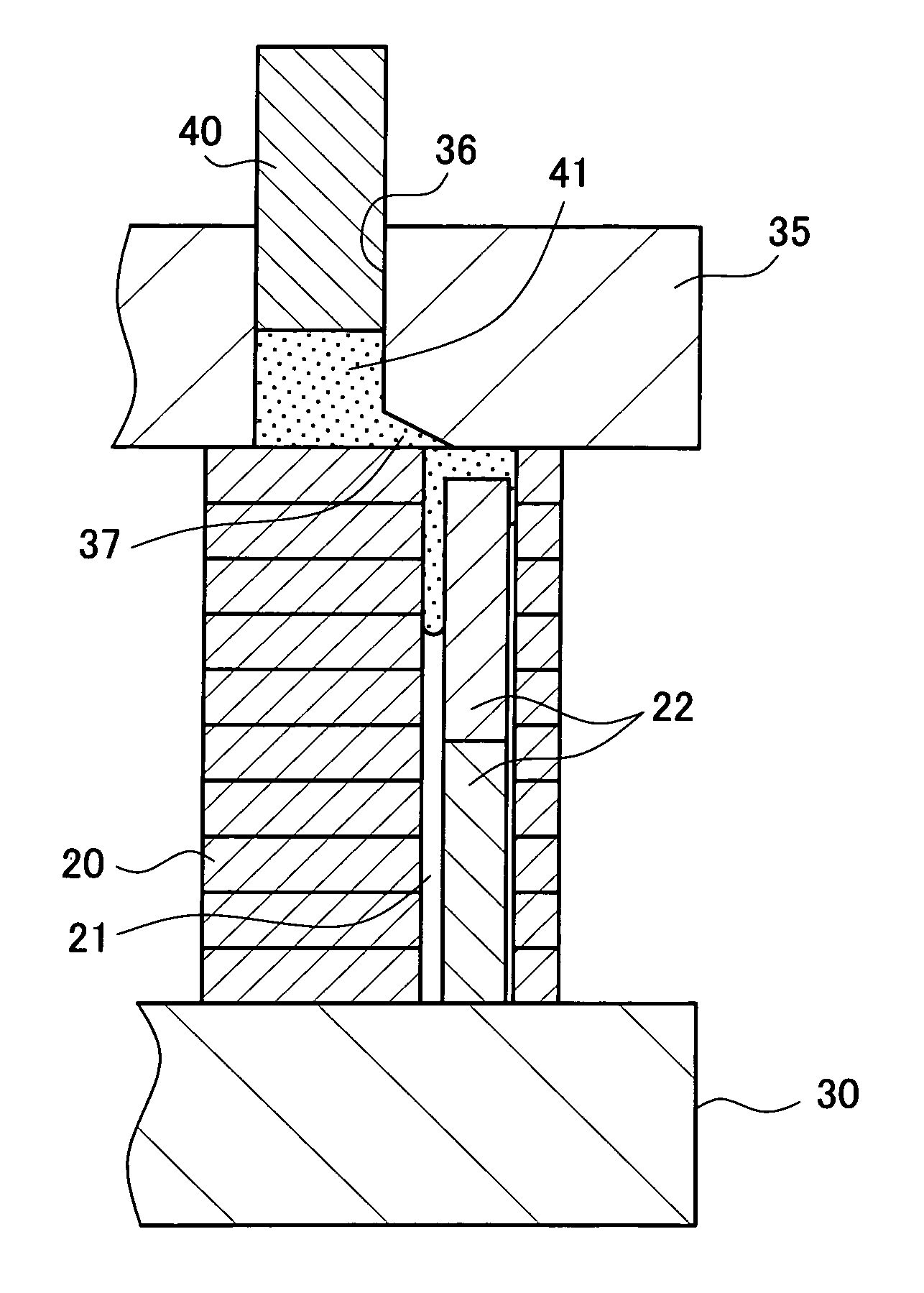
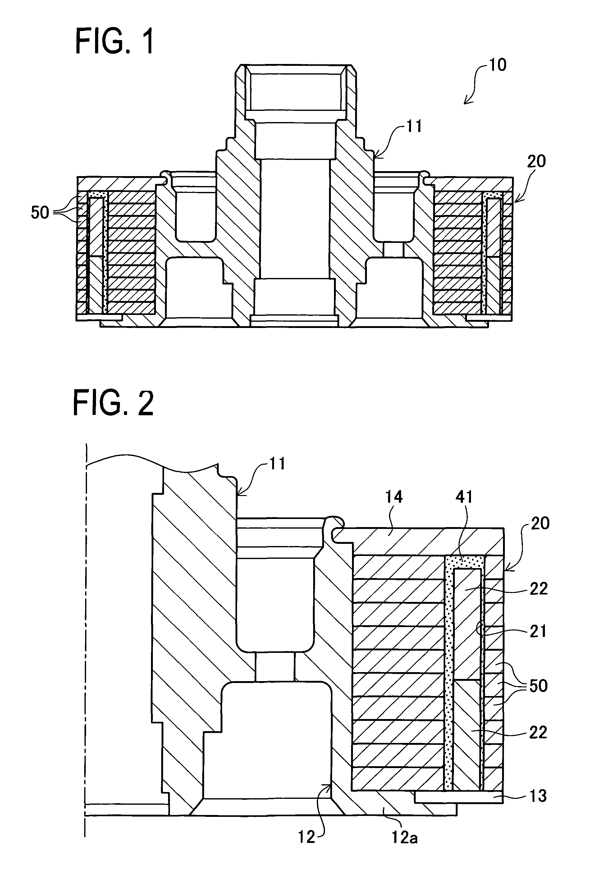
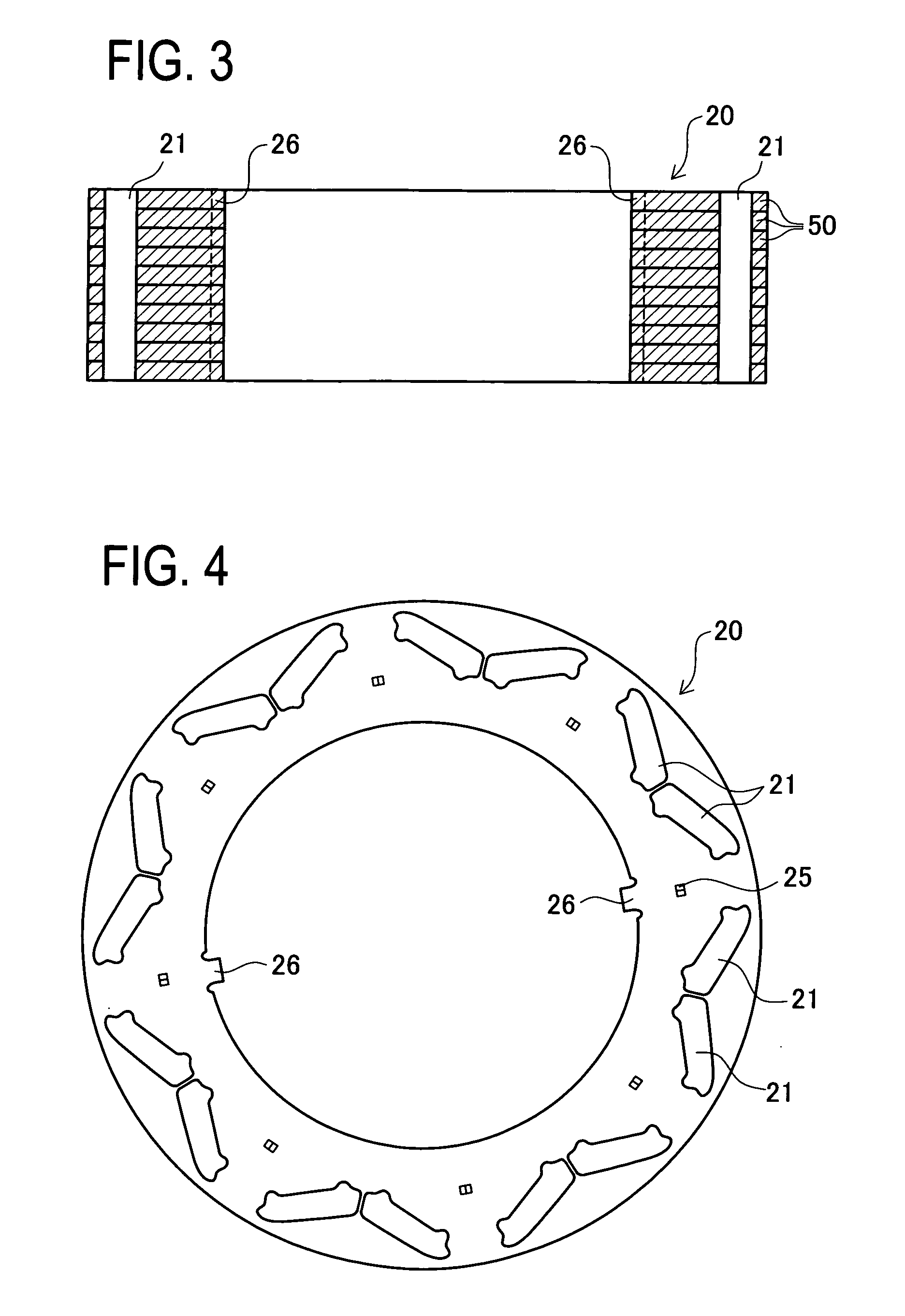
[0065]A detailed description of a preferred embodiment of a rotor manufacturing method embodying the present invention will now be given referring to the accompanying drawings. A rotor manufactured by the rotor manufacturing method of the invention will be first explained with reference to FIGS. 1 and 2. FIG. 1 is a sectional view of a schematic configuration of the rotor. FIG. 2 is a view of a rotor core mounting part in the rotor. A rotor 10 includes an annular rotor shaft 11 engageable with a rotary shaft of a motor, and a hollow cylindrical rotor core 20 mounted on the rotor shaft 11. The rotor core 20 is fixedly fitted on an outer periphery of a core holding part 12 of the rotor shaft 11 as shown in FIG. 2. In this state, a lower surface of the rotor core 20 is supported by a flange 12a of the core holding part 12. A magnet end 13 is placed under and around a magnet containing hole 21 formed in the rotor core 20. On the other hand, an upper surface of the rotor core 20 is press...


PUM

PropertyMeasurementUnit
thicknessaaaaaaaaaa
sizeaaaaaaaaaa
thicknessaaaaaaaaaa

Abstract

An object is to provide a rotor manufacturing method capable of reducing a rotor unbalance amount by controlling a magnet arrangement position in a rotor core and improving work efficiency when fixing a magnet to the rotor core by using resin. A lower surface of a rotor core is arranged in a lower mold. A magnet is arranged in a lower mold. A magnet is contained in each of magnet containing holes formed in the rotor core in such a manner that a predetermined space is assumed between an upper surface of the rotor core and an upper surface of the magnet. An upper mold is arranged on the upper surface of the rotor core. The upper mold and the lower mold apply a pressure to the rotor core and a molten resin is supplied with pressure from an internal diameter side via the predetermined space into the plurality of magnet containing holes from respective cylinder arranged in the upper mold. Thus, the magnets are molded by resin while pressing the magnets toward the outer diameter side of the magnet containing holes.

Description

CROSS-REFERENCE TO RELATED APPLICATIONS[0001]This is a national phase application filed under 35 U.S.C. 371 of PCT / JP2007 / 052425 filed on Feb. 5, 2007, which claims the benefit of priority from the prior Japanese Patent Application No. 2006-031415 filed on Feb. 8, 2006, the entire contents of all of which are incorporated herein by reference.FIELD OF THE INVENTION[0002]The present invention relates to a method of manufacturing a rotor to be used in a motor and more particularly to a method of manufacturing a rotor in which a magnet is fixed to a rotor core with resin.BACKGROUND OF THE INVENTION[0003]For fixing a magnet to a rotor core of a rotor to be used in a motor, there is a method of fixing the magnet to the rotor core with resin. One of such techniques of fixing the magnet with resin is disclosed in for example JP2001-298887A. In this technique, as shown in FIGS. 20 and 21, a rotor 101 is configured such magnets 111 are fixed to a rotor core 112 with resin supplied between adj...

Claims


Application Information

Patent Timeline
Patent Type & Authority Patents(United States)
IPC IPC(8): H02K15/02
CPCH02K1/2766H02K15/03H02K15/165H02K15/12Y10T29/49009Y10T29/53143Y10T29/49012H02K1/22H02K1/27
Inventor FUKUMARU, KENICHIROAMANO, KATSUMIFUKUMOTO, TAKASHIUEDA, KAZUTOSHIHARUNO, KENTAROTAKEUCHI, TAKETOWATANABE, ATSUSHI
Owner TOYOTA JIDOSHA KK
Why Eureka
Try Eureka