Belt link with half the surface inclined

a belt link and half-surface technology, applied in the direction of conveyors, transportation and packaging, etc., can solve the problems of material thickness and material density around the eye parts that have to be substantial, and achieve the effect of increasing material thickness or density

Active Publication Date: 2011-09-20
AMMERAAL BELTECH MODULAR
View PDF7 Cites 2 Cited by
  • Summary
  • Abstract
  • Description
  • Claims
  • Application Information

AI Technical Summary

Benefits of technology

[0008]It is therefore an object of the present invention to provide a chain link as well as a conveyor belt assembly where heavy loads may be transferred between adjacent chain links without substantially increasing the material thickness or density.DESCRIPTION OF THE INVENTION
[0010]In this configuration it is possible to provide more eye parts over a wider distance perpendicular to the travelling direction of the conveyor belt such that the aggregated load from the objects carried on the conveyor belt and thereby the conveyor chain links will be distributed across more eye parts whereby the relative load per eye part and thereby also the impact on the transfers pin arranged to connect adjacent chain links in the belt will be lessened. Furthermore, by providing one-sided inclination on the belt links the size of the belt links may also be relatively small such that the manufacturing process does not involve very heavy and large injection moulding equipment with the additional costs involved.
[0014]The vertical load will be transmitted by the chain link through the substructure. The larger the contact area is between the chain link and the substructure, the lesser the load per area unit has to be absorbed by the substructure. Therefore, the flat section in combination with the relatively stiff construction of the chain link will distribute the load placed on the conveyor surface to a larger area in the substructure and thereby minimize the impact on the substructure. The load in the direction of travel, i.e. in the plane of the conveyor will also be lessened in that as the flat section also is provided with eye parts and openings the eye parts available for transferring the load to an adjacent chain link is increased such that the load on each eye part will be lessened.
[0016]By providing the side edges with identical height it becomes possible to combine chain links in a brick laying pattern without creating abrupt differences in height on the conveying surfaces and at the same time by providing the inclination at the intervals mentioned, a relatively flat valley is created between two adjacent chain links arranged as mirror images, but depending of the diameter of the object to be conveyed on the conveying surface tests have indicated that the relative shallow inclination does provide a very decisive support such that the objects may safely be conveyed on the conveying surface.
[0017]In a further advantageous embodiment this mirror image is created by using two chain links where the inclination on one is mirrored on the other, such that by assembling two chain links laterally the inclinations will form a valley. This effect is created for example by rotating one link relative to the other, such that the leading edge becomes the trailing edge on one and not the other link, or by providing two types of links where one is a mirror image of the other.

Problems solved by technology

One problem, however, associated with these types of links is the fact that in order to carry the very heavy loads and thereby transfer the loads from chain link to chain link by means of transverse pins inserted through apertures arranged laterally in the eye parts of the belt links, the material thickness as well as material density around the eye parts have to be substantial in order to transfer the very heavy loads.

Method used


Image

  • Belt link with half the surface inclined
  • Belt link with half the surface inclined
  • Belt link with half the surface inclined

Examples


Embodiment Construction

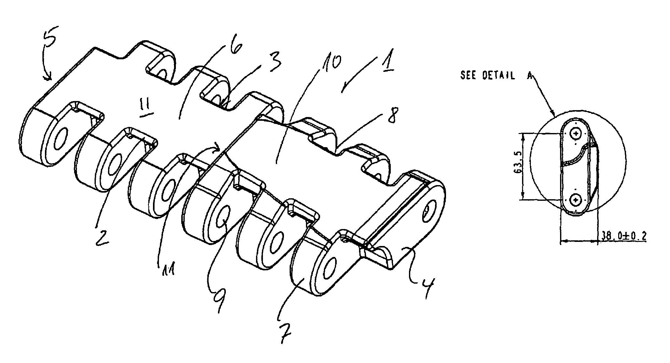
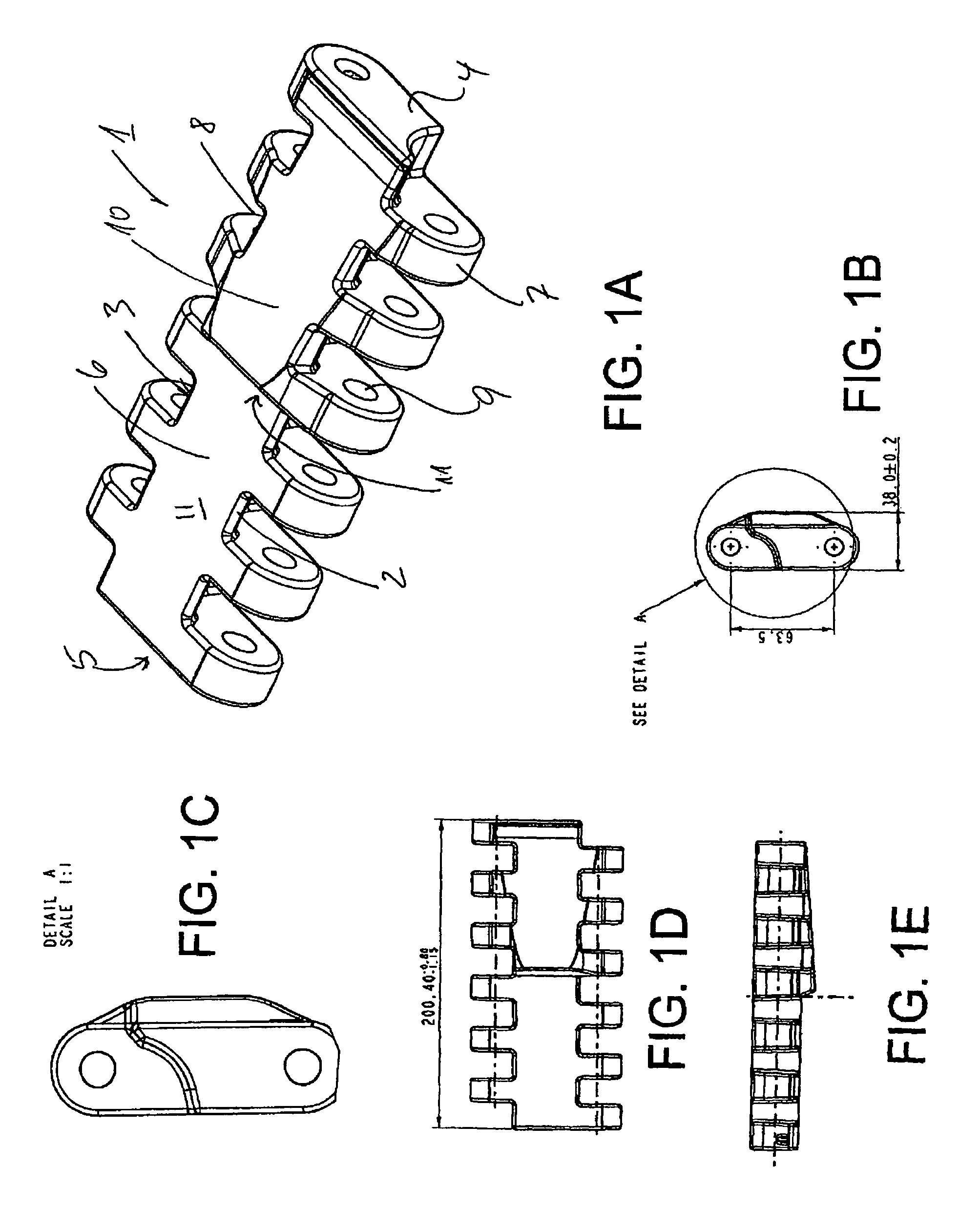
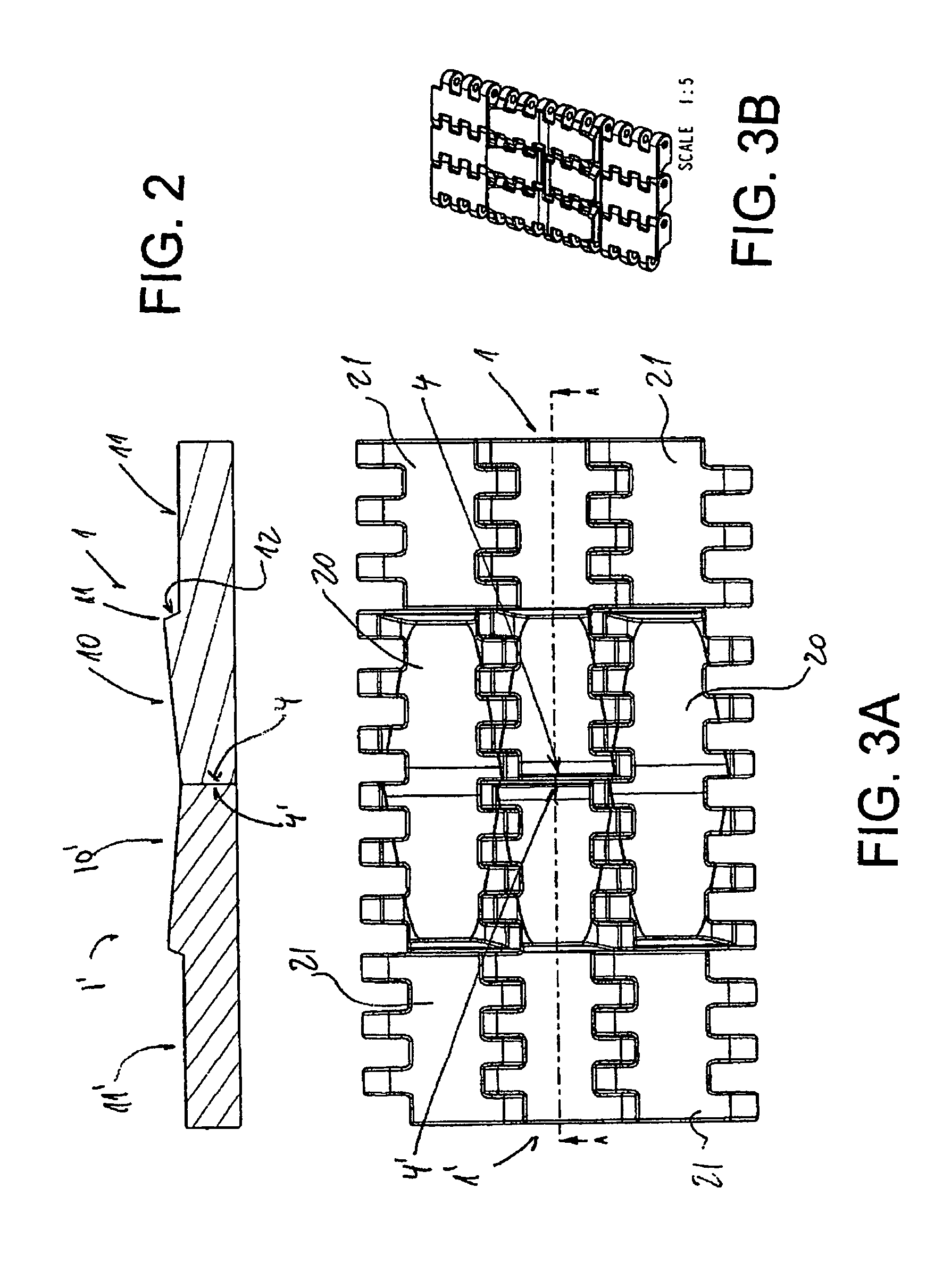
[0009]The present invention addresses this by providing a chain link where the link is defined by a leading edge, a trailing edge, two opposed side edges, a load carrying upper surface, and a bottom face, wherein along the leading edge is provided a plurality of eye parts separated by openings and where the link along the trailing edge is provided with a plurality of eye parts separated by openings, such that the eye parts on the trailing edge of one belt link may be arranged in the openings arranged on the leading edge of an adjacent belt link, and the belt links may be connected either by inserting a traverse rod through apertures provided in the lateral direction in the eye parts or by fitting lateral notches provided on the sides of the eye parts along one edge in slots provided on the sides of the eye parts on the opposite edge, and wherein between the leading and trailing edge and the side edges a load carrying surface is defined, where said surface at least for a part of the ...


PUM


Abstract

A conveyor chain link has a leading edge, a trailing edge, two opposed side edges, a load carrying upper surface and a bottom face. The leading and trailing edges have pluralities of eye parts separated by openings, such that the trailing edge of one belt link may be arranged in the openings arranged on the leading edge of an adjacent belt link. The belt links are connected either by inserting a traverse rod through apertures in the eye parts or by fitting lateral notches in slots provided in sides of the eye parts on the opposite edge on the sides of the eye parts along one edge. Between the leading and trailing edges and the side edges at least a part of a load carrying surface has a one-sided inclination towards one side edge.

Description

[0001]This application claims the benefit of Danish Application No. PA 2007 00721 filed May 14, 2007, which is hereby incorporated by reference in its entirety.FIELD OF THE INVENTION[0002]The present invention relates to a conveyor chain link as well as a conveyor belt built up of a number of such chain links.BACKGROUND ART[0003]In the art conveyors are used for a multitude of purposes and there are numerous specially designed chain links depending on the tasks at hand.[0004]For one particular use special belt links are the most appropriate and the present invention is particularly directed to chain links for use in conveyors where cylindrical very large and / or heavy loads are to be transported on the conveyor. Such loads may include rolls of printing paper for printing presses, drums, but will not be limited to the mentioned products.[0005]In order to transport this type of product the top surface of the belt has traditionally been shaped to accommodate and retain the products on t...

Claims


Application Information

Patent Timeline
Patent Type & Authority Patents(United States)
IPC IPC(8): B65G17/06
CPCB65G17/08B65G17/40
Inventor ANDERSEN, KENNETH WESTERGAARDBROE, PETER
Owner AMMERAAL BELTECH MODULAR
Why Eureka
Try Eureka