

Liquid crystal display device
a liquid crystal display and display portion technology, applied in the direction of optics, polarising elements, instruments, etc., can solve the problems of misalignment, non-fixation of the display portion, etc., and achieve the effect of reducing the warp in the liquid crystal display portion due to an external environment, without increasing the material cost and the thickness of the liquid crystal display device, and without losing mechanical reliability
- Summary
- Abstract
- Description
- Claims
- Application Information
AI Technical Summary
Benefits of technology
Problems solved by technology
Method used
Image

Examples
example 1
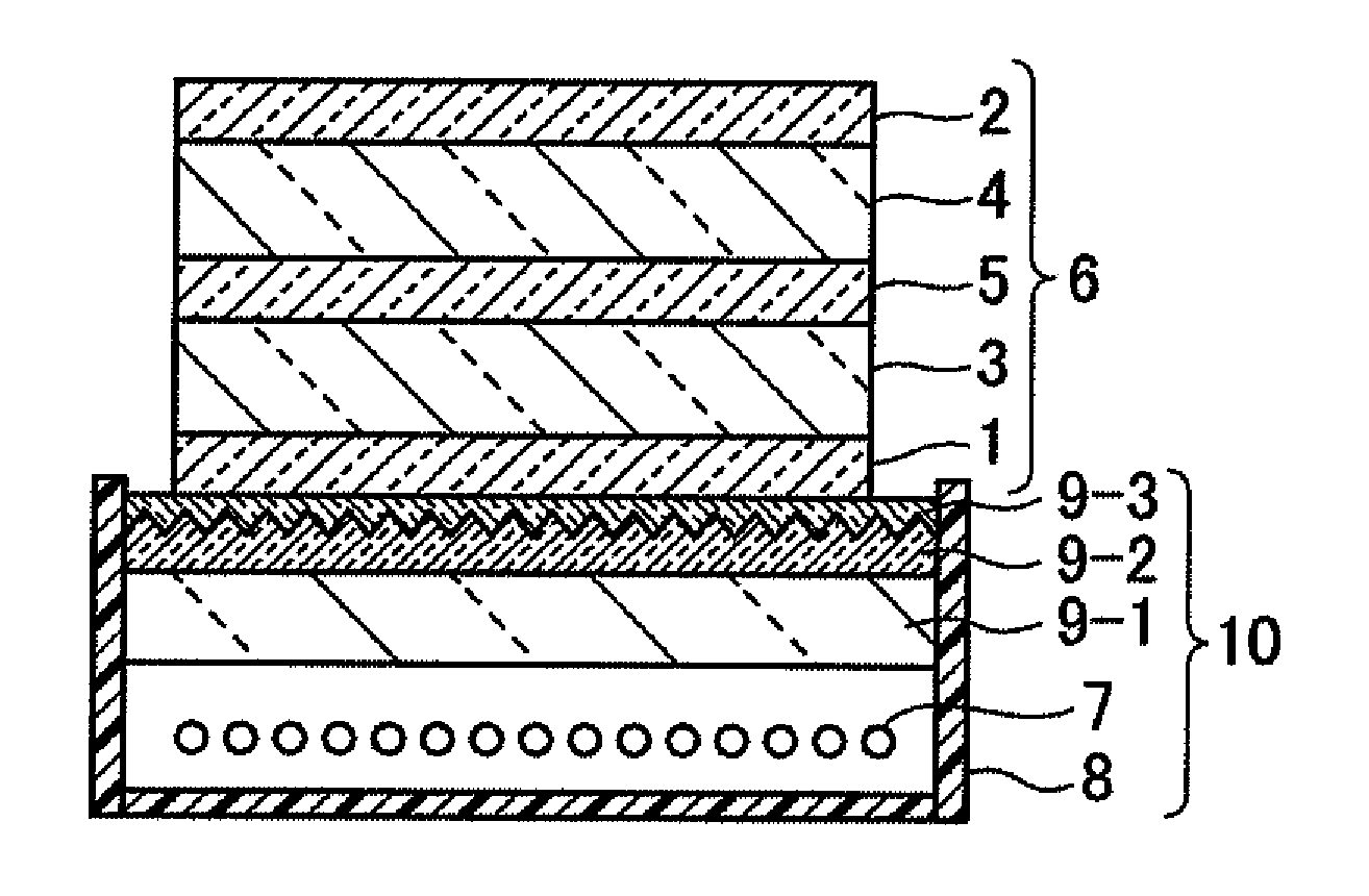
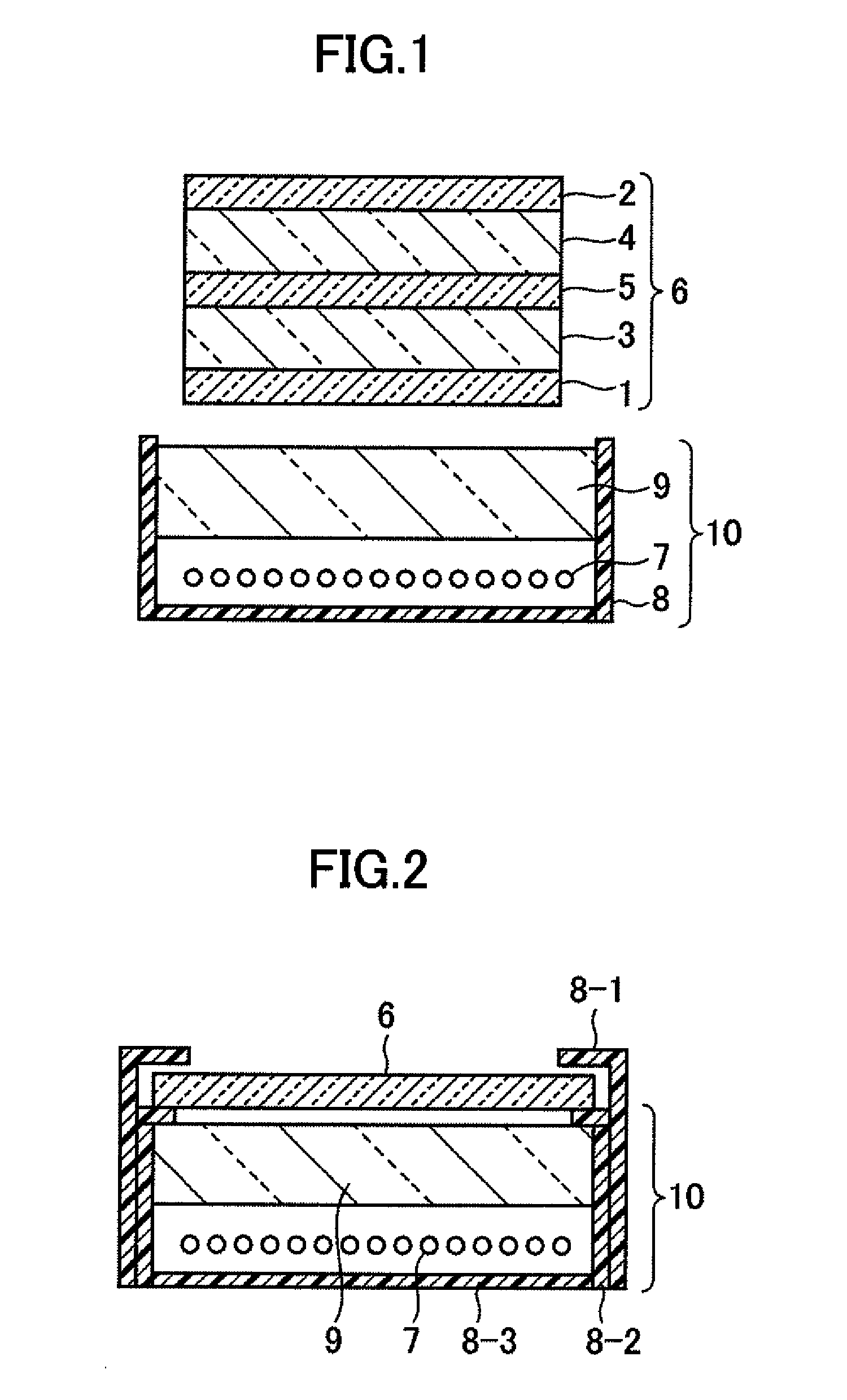
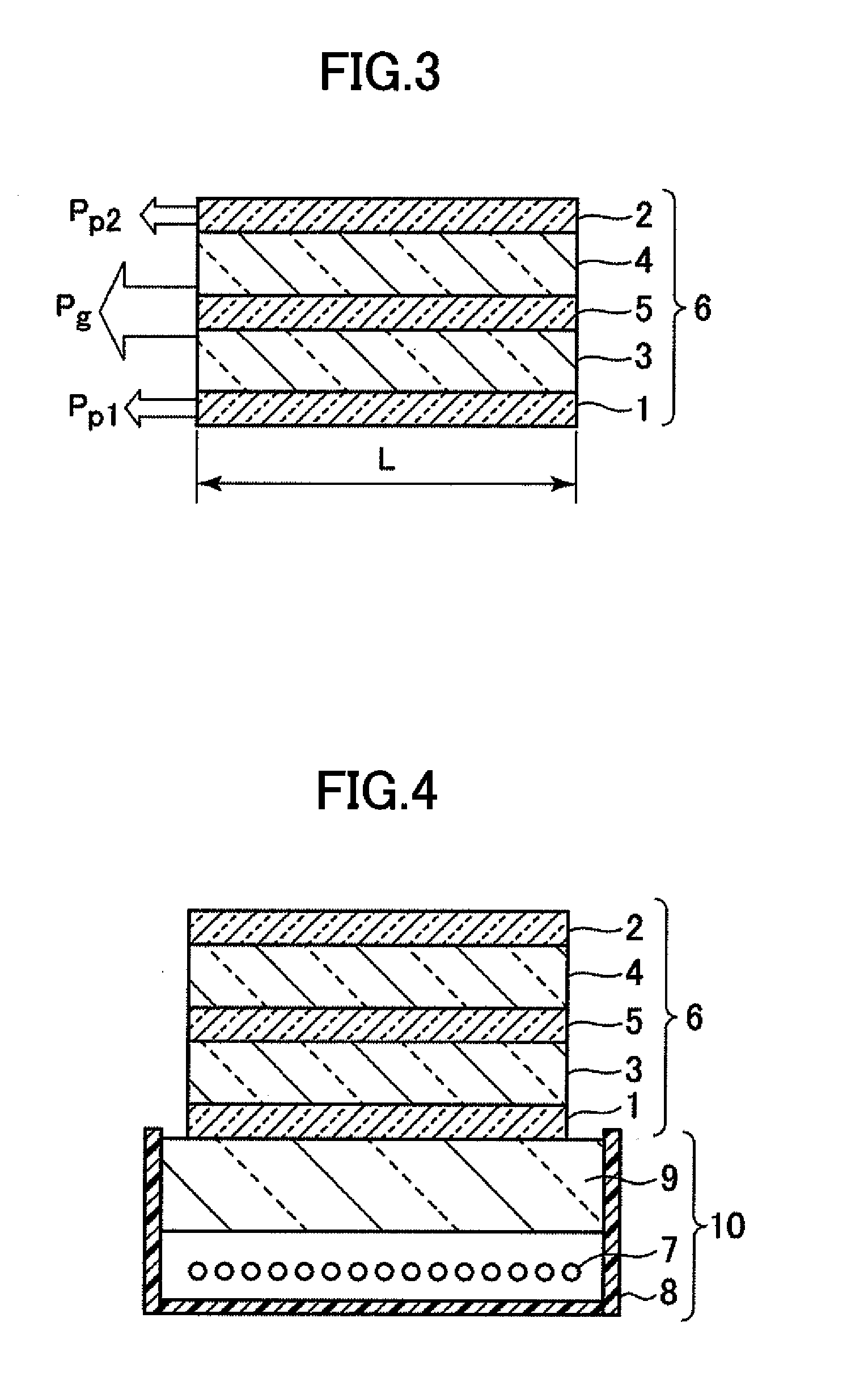
[0089]FIG. 11 illustrates a structure of this example. In FIG. 11, a backlight device 10 is of a side edge type in which a light source 7 is provided at an end portion of the backlight device and light emitted from the light source is guided by a light guide plate 9-4 in a plane direction and is taken out to a front side. As the light source 7, a white light-emitting-diode (LED) is used. A reflector 12 reflects light emitted from the light source and makes the light efficiently enter the light guide plate. The light guide plate is formed of glass. In order to make directional light emitted from the liquid crystal display device, a prism sheet 9-2 is provided on the light guide plate 9-4. Both a bottom surface and a top surface of the prism sheet 9-2 are coated with a low refractive index layer 9-3 having a refractive index of 1.15.
[0090]The thickness of a first polarizing plate 1 and a second polarizing plate 2 is 0.2 mm. The absorption axis of the first polarizing plate 1 is in par...
example 2
[0092]FIG. 14 illustrates a structure of this example. In this example, differently from the case of Example 1, as in the conventional case, the liquid crystal display portion 6 and the optical member group 9 are not joined together. A poly-ethylene-terephtalate (PET) film 13 is joined to the first polarizing plate 1 so as to be in intimate contact therewith.
[0093]The Young's modulus of the first polarizing plate 1, the second polarizing plate 2, the glass substrates 3 and 4, and the PET film 13 which were used were 2 GPa, 1.8 GPa, 71 GPa, and 1.6 GPa, respectively. The thicknesses of the first polarizing plate 1, the second polarizing plate 2, and the glass substrates 3 and 4 were 0.2 mm, 0.2 mm, and 0.7 mm, respectively. The strains per unit length on the first polarizing plate 1, the second polarizing plate 2, and the PET film 13 under a high temperature and high humidity environment were 0.00953, 0.0142, and 0.003, respectively.
[0094]When the PET film was not provided, the shape...
example 3
[0095]FIG. 17 illustrates a structure of this example. A surface with a prism structure of the prism sheet 9-2 is coated with the low refractive index layer 9-3 having a refractive index of 1.15. The prism sheet 9-2, the low refractive index layer 9-3, and the liquid crystal display portion 6 are joined together so as to be in intimate contact with one another via an adhesive. In this example, an optical member group 9 except for the prism sheet is not joined to the liquid crystal display portion 6.
[0096]As the first polarizing plate 1, the second polarizing plate 2, and the glass substrates 3 and 4, ones similar to those of Example 2 were used. A support base of the prism sheet 9-2 was a PET film having a thickness of 0.25 mm. The shape of the warp in the liquid crystal display portion under a high temperature and high humidity environment was as illustrated in FIG. 18. In FIG. 18, the horizontal axis represents the position x of the liquid crystal display portion in the long side ...
PUM
 Abstract
Description
Claims
Application Information