Needleless injection structure

a technology of injection structure and needle, which is applied in the direction of couplings, other domestic objects, and catheters, etc., can solve the problems of patent discomfort, infection hazards, and loading to prime cost, and achieve the effects of reducing prime cost, improving safety, and good mitigating patient pain

Inactive Publication Date: 2011-09-20
HUANG SHU FANG
View PDF8 Cites 24 Cited by
  • Summary
  • Abstract
  • Description
  • Claims
  • Application Information

AI Technical Summary

Benefits of technology

[0005]In view of the aforementioned issues, the present invention provides a needleless injection structure for the improvement of the use of the safety. In addition, the needleless injection structure according to the preset invention can make cost saving and discomfort mitigation.
[0007]The trough channel is formed in the duct; the stuff base is disposed at the top of the duct; the casing is assembled to the duct; the casing has the opening communicating the accommodating space; and the stuff base is disposed in the accommodating space are disclosed in the present invention. The following beneficial effects according to the needleless injection structure of the present invention are described as following: Needleless could improve the use of the safety and diminish the prime cost. The stuff base possesses the buffer of compression and decompression for the drug, which is good at mitigating the pain of the patient while in injection. In addition, the guiding angle of the second fillet of the casing is less than that of the first fillet of the stuff base, so that a tight fit is offered thereby in order to prevent the drug reflux. Furthermore, the closed space is formed in the stuff base to increase the restoring capability of the stuff base. The buffering area is formed at the top of the closed space, the expansion deformation measurement of the stuff base would be decreased, which prevent the drug blocking from the over-expansion of the stuff base.

Problems solved by technology

However, the needle 21a is acute and possesses the hazards of infection for someone if stabbed.
Besides, the used needles are treated as medical disposals, which is a loading to prime cost.
Furthermore, the injection with the needle 21a provides the injecting act too fast to cause the discomfort of the patent.

Method used


Image

  • Needleless injection structure
  • Needleless injection structure
  • Needleless injection structure

Examples


Embodiment Construction

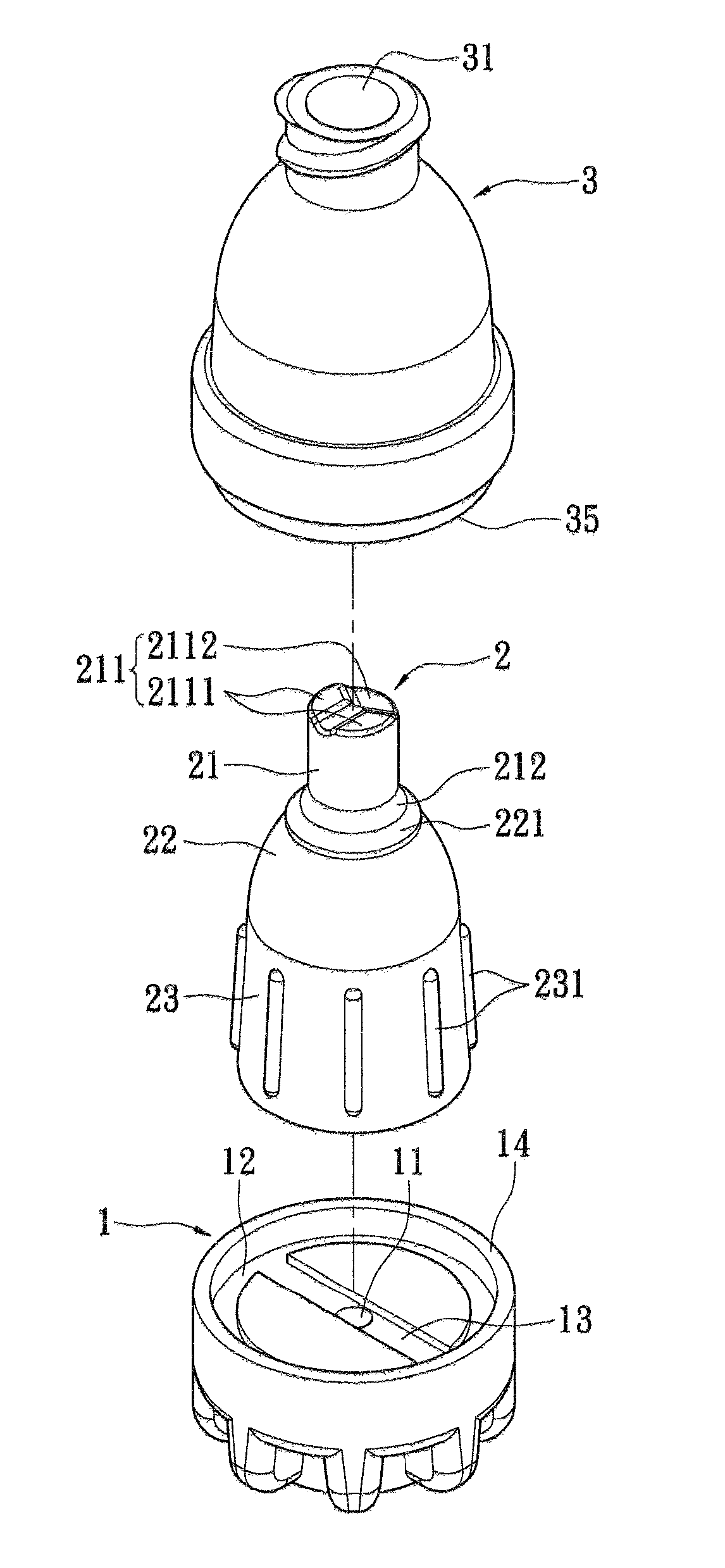
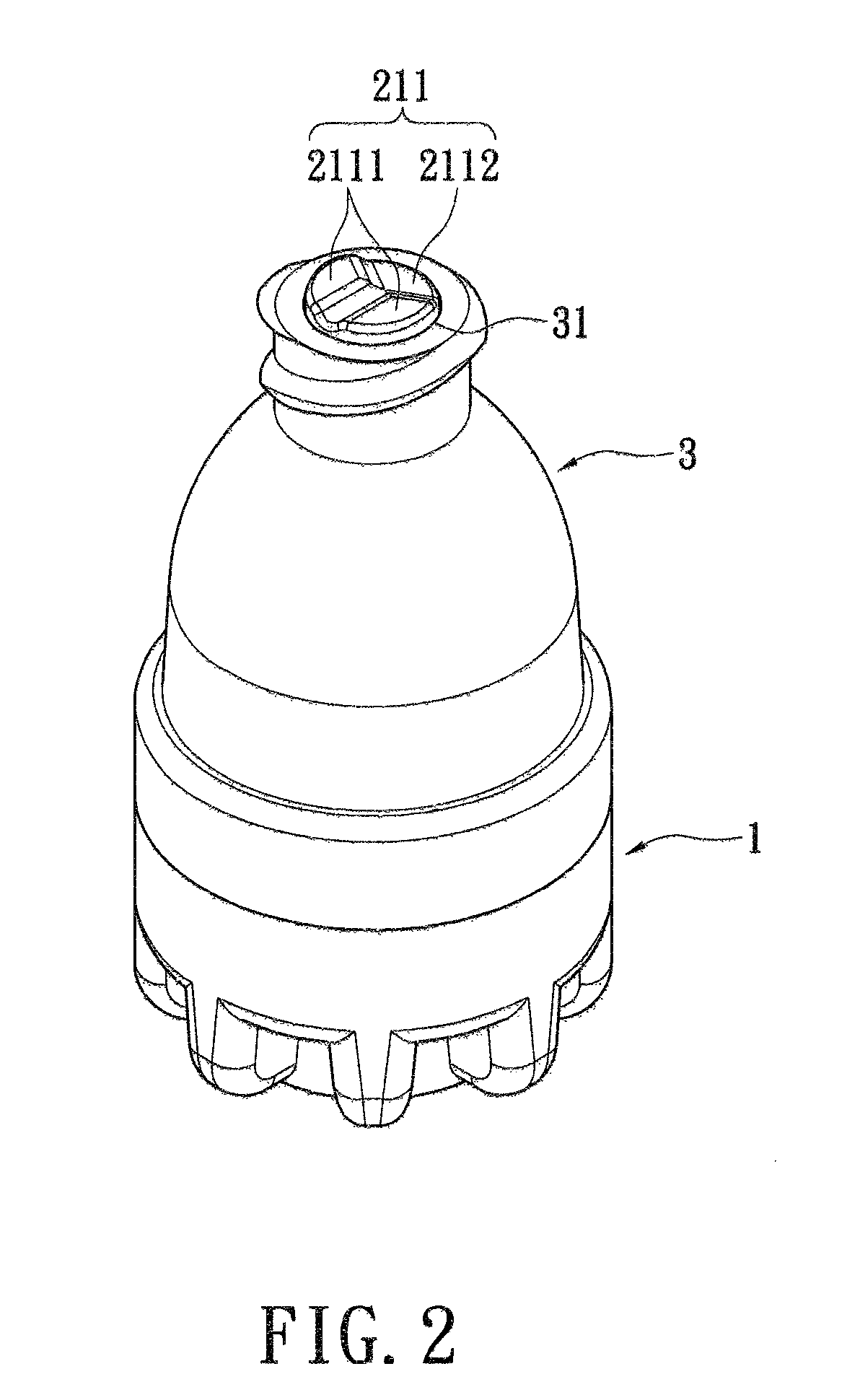
[0022]Referring now to FIGS. 2 to 8, in which a needleless injection structure according to the present invention is disclosed. The needleless injection structure, applied to medical tools for blood transfusion or infusion, includes a duct 1, a stuff base 2 and a casing 3. The duct 1 has a through channel 11 extending a top through a bottom thereof The duct 1 has a ring channel 12 and a strip-liked transverse channel 13 both indented on the top thereof. The duct 1 has a first connection portion 14 annularly protruding at the top thereof. The transverse channel 13 is formed within the ring channel 12 for guiding the liquid. The transverse channel 13 communicates the ring channel 12 with the through channel 11. The first connection portion 14 is disposed around the ring channel 12.

[0023]In this embodiment, the stuff base 2 can be made of silicone materials, and other resilient materials. The stuff base 2 is disposed on the top of the duct 1. The stuff base 2 has an upper section 21, a...


PUM

PropertyMeasurementUnit
pressureaaaaaaaaaa
areaaaaaaaaaaa
guide angleaaaaaaaaaa

Abstract

A needleless injection structure includes a duct, a stuff base and a casing. The duct has a through channel. The duct has a ring channel and a transverse channel formed on a top thereof. The stuff base is disposed on the top of the duct. The stuff base has an uneven portion, a first fillet, a plurality of first protrusions and a closed space. The casing is assembled on the duct. The casing has an opening, a second fillet, an accommodating space and a plurality of second protrusions. The opening communicates with the accommodating space. The stuff base stays in the accommodating space. The improved needleless injection structure is provided thereby, which results in increasing the use of safety, saving the cost, and mitigating the pain of the patient.

Description

BACKGROUND OF THE INVENTION[0001]1. Field of the Invention[0002]The present invention relates to a needleless injection structure, in particular, to a needleless injection structure, which is applied to a medical tools for blood transfusion or infusion.[0003]2. Description of Related Art[0004]Referring to FIG. 1, in which a conventional duct la is illustrated. The conventional duct 1a, which is hollow, has an opening 11a, and a stuff 12a filled in the opening 11a. The stuff 12a is resilient. When medical professionals intend to do some drug injections, the drug is inhaled into a syringe 2a first. Piercing the needle 21 a of the syringe 2a into the duct 1a and pushing a plunger 22a to force the drug into the duct 1a. However, the needle 21a is acute and possesses the hazards of infection for someone if stabbed. A needleless injection structure may be one solution to this problem. Besides, the used needles are treated as medical disposals, which is a loading to prime cost. Furthermore...

Claims


Application Information

Patent Timeline
Patent Type & Authority Patents(United States)
IPC IPC(8): A61M25/16
CPCA61M39/26B29C43/14A61M39/04A61M2039/1077A61M2039/263A61M2207/00B29C2043/142B29K2021/00B29K2083/00B29L2031/712B29L2031/7544
Inventor HUANG, SHU-FANG
Owner HUANG SHU FANG
Why Eureka
Try Eureka