Axial load limiting system and methods

a technology applied in the field of limiting system and limiting method, can solve problems such as the rotation of rods and surgical implements

Inactive Publication Date: 2011-09-20
KYPHON
View PDF109 Cites 28 Cited by
  • Summary
  • Abstract
  • Description
  • Claims
  • Application Information

AI Technical Summary

Benefits of technology

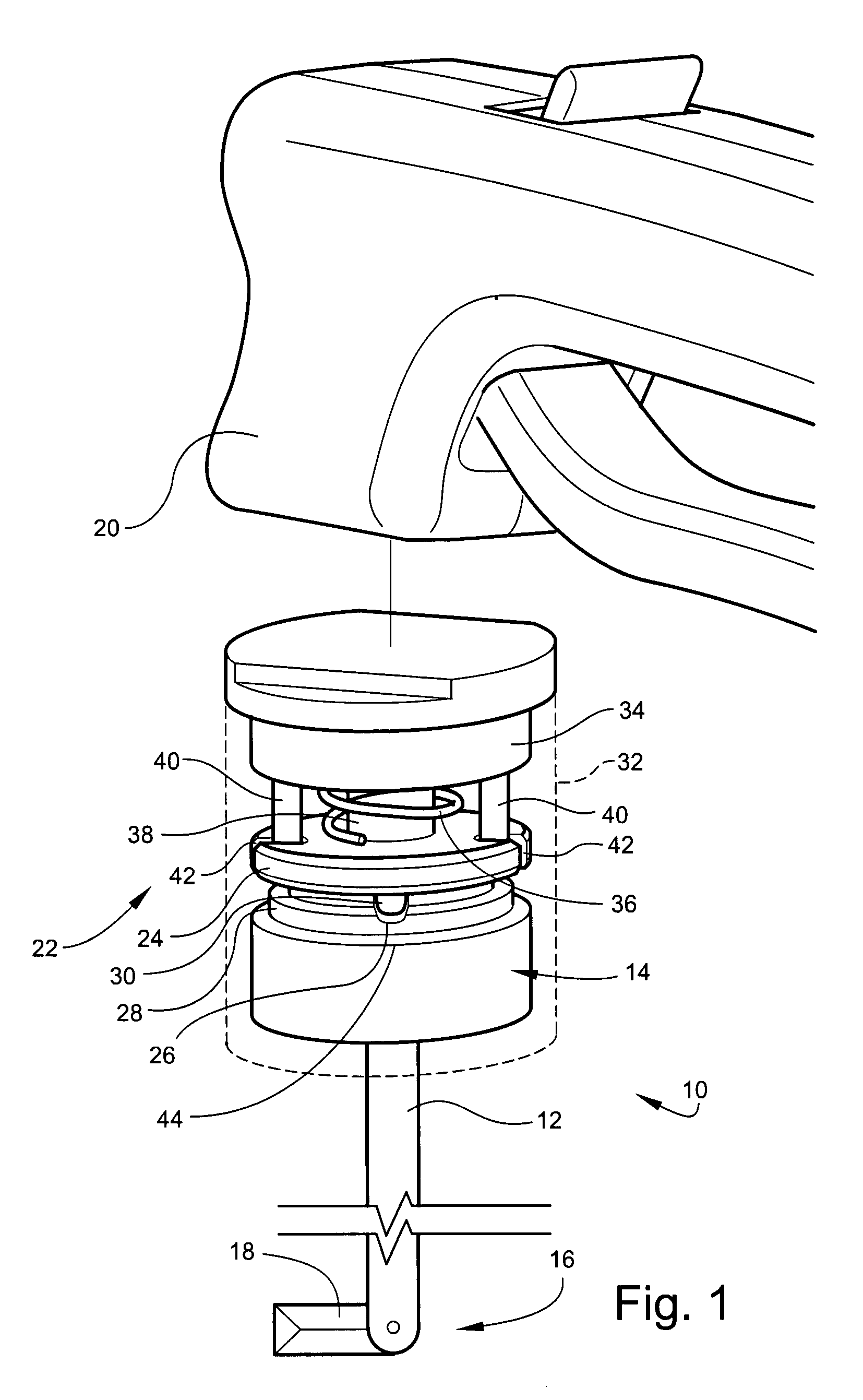
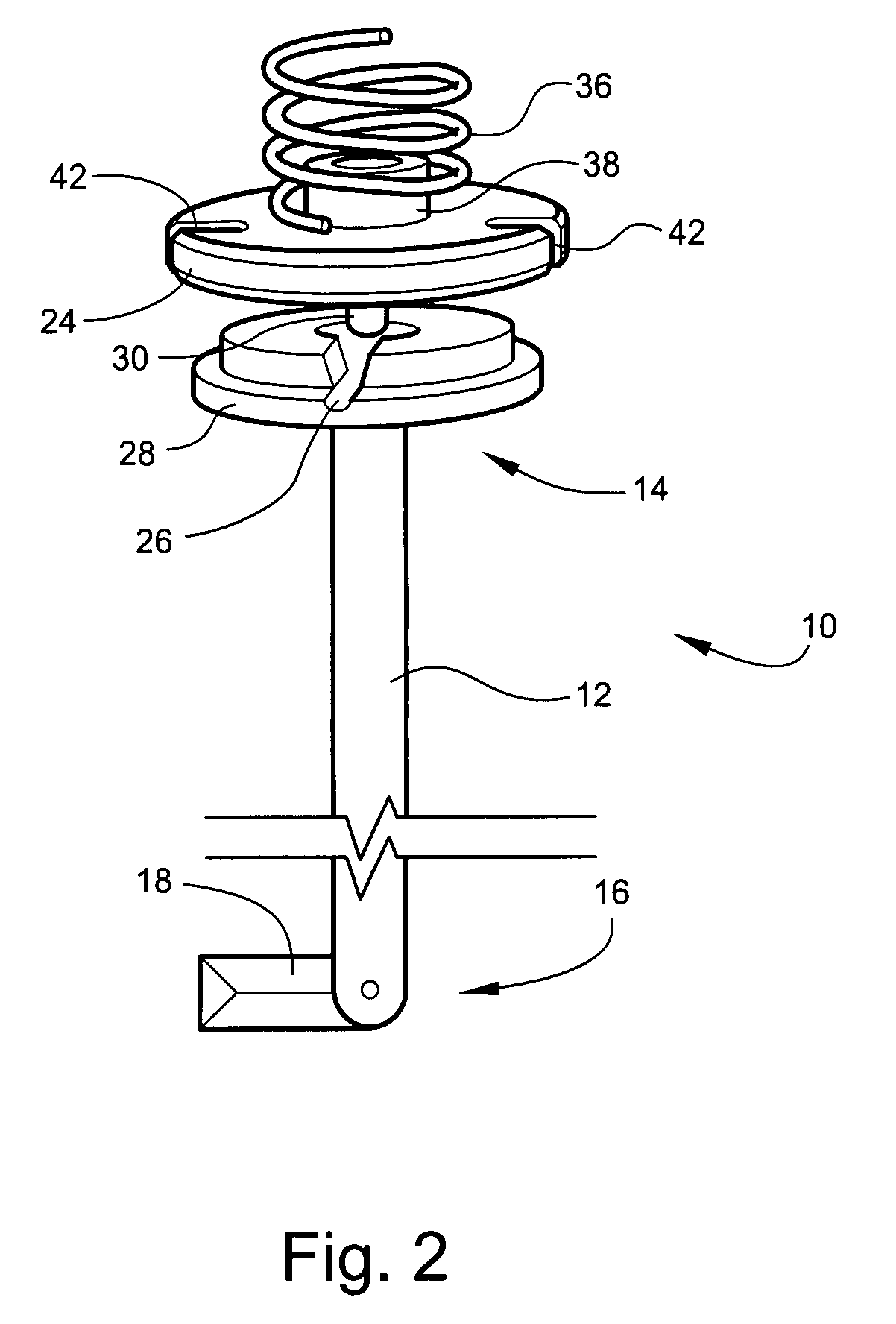
[0010]In an illustrative embodiment, a surgical device can include a rod attached on one end to a rotatable handle and attached on the opposite end to a surgical implement, for example, a curette. A first torque limiting element can be connected to the handle. A second torque limiting element can be operably connected to the rod and surgical implement and releasably engageable with the first torque limiting element. When the first and second torque limiting elements are engaged, rotation of the handle can cause rotation of the rod and surgical implement. When a rotational force that exceeds a predetermined torque limit is applied to the handle, the first and second torque limiting elements can disengage from each other, so that the handle is rotatable without rotation of the rod and surgical implement. After becoming disengaged, the first and second torque limiting elements may be re-engaged so that further rotation of the handle can cause rotation of the rod and surgical implement. In this manner, an embodiment of the surgical device can be protected from damage and / or inoperability related to application of an excessive rotational torque to the device. In addition, an embodiment of the device may be re-engaged for further rotation of the surgical implement without removing the device from a surgical site.
[0011]In an embodiment, the first torque limiting element can comprise a first substantially planar surface, and the second torque limiting element can comprise a second substantially planar surface. The first and second planar surfaces can be biased against each other, for example, with a spring, such that, within a predetermined torque range, rotation of the first planar surface can cause rotation of the second planar surface in the same direction through frictional engagement of the surfaces. The first and second planar surfaces can be releasably engageable with each other. When a predetermined torque limit is surpassed, the two surfaces can become disengaged such that the first planar surface can rotate independently of the second planar surface. By decreasing the rotational force applied to the first planar surface, the first and second planar surfaces can become re-engaged through frictional engagement so that rotation of the first planar surface can cause rotation of the second planar surface.
[0012]In certain embodiments, the first planar surface can include a projection that is matingly engageable with a projection receiving notch in the second planar surface. The projection and the notch can be releasably engageable with each other. When the projection and the notch are engaged, rotation of the first planar surface can cause rotation of the second planar surface. When a predetermined torque limit is surpassed, the projection and the notch can become disengaged such that the first planar surface can rotate independently of the second planar surface. Upon further rotation of the first planar surface, the projection can be re-engaged with the notch such that rotation of the first planar surface can cause rotation of the second planar surface.
[0013]In some embodiments, the first torque limiting element can include a ball plunger attached to the handle and comprising a ball biased toward the second torque limiting element. The second torque limiting element can include a ball engaging receptacle attached to the rod for releasably engaging the ball plunger ball. In certain embodiments, the ball plunger can be positioned substantially perpendicular to the rod. When the ball plunger ball and the ball engaging receptacle are engaged, rotation of the handle can cause rotation of the rod and surgical implement. When a predetermined torque limit is surpassed upon rotation of the handle, the ball plunger ball and the ball engaging receptacle can become disengaged such that the handle can rotate independently of the rod and surgical implement. Upon further rotation of the handle, the ball plunger ball can be re-engaged with the ball engaging receptacle such that rotation of the handle can cause rotation of the rod and surgical implement.
[0015]Some embodiments of the present invention can include a method of using a surgical tool having a torque limiting device comprising a rod rotatingly engageable on one end with a handle and attached on the opposite end to a surgical implement. A first torque limiting element can be connected to the handle and engageable with a second torque limiting element operably connected to the surgical implement. The surgical implement and a portion of the rod can be inserted into an interior body region, and a first rotational force applied to the handle to rotate the surgical implement. When a second rotational force that exceeds a predetermined torque limit is applied to the handle, the first element can become disengaged from the second element such that the handle rotates without rotation of the surgical implement. Once the two torque limiting elements are disengaged, the handle can be rotated to re-engage the first element with the second element so that further rotation of the handle causes rotation of the surgical implement.
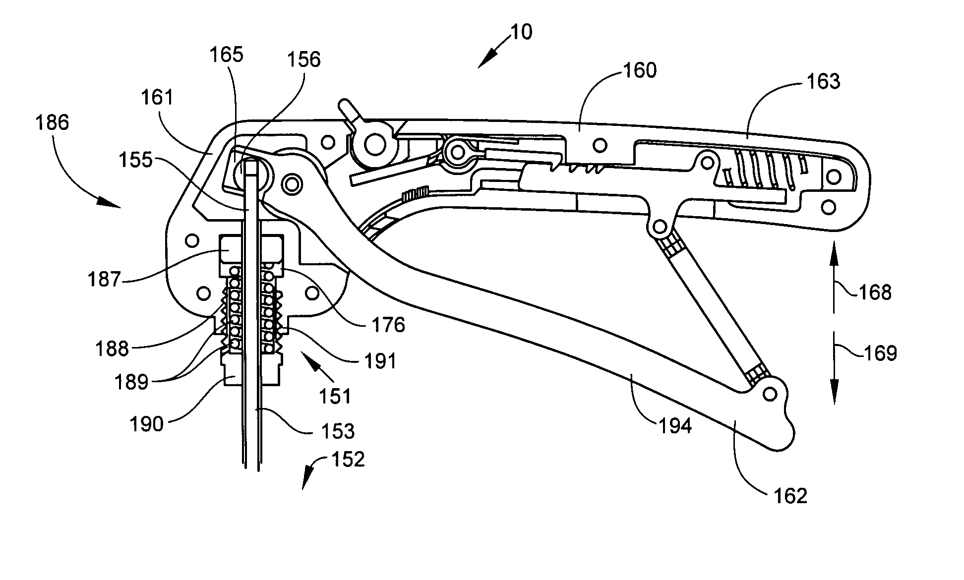
[0017]Some embodiments of the present invention can include a method of using a surgical tool having an axial load limiting system. After the surgical tool has been inserted into an interior body region, such as a vertebral body, the lever can be pivoted relative to the handle to pivot the surgical implement. When further pivoting of the surgical implement is restricted due to an obstruction, such as hard tissue, an excessive axial load can be applied to the rod. The excessive axial load can cause the rod, surgical implement, and shaft to be moved in a distal direction so as to compress the biasing mechanism. In this manner, the excessive axial load can be absorbed by the biasing mechanism, thereby relieving the rod, surgical implement, and other attached structures of the surgical tool of the excessive axial load. In an embodiment of such a method in which the surgical implement comprises a curette tip, the handle may be rotated so as to rotate the curette tip and scrape tissue at a surgical site.

Problems solved by technology

When the first and second torque limiting elements are engaged, rotation of the handle can cause rotation of the rod and surgical implement.

Method used


Image

  • Axial load limiting system and methods
  • Axial load limiting system and methods
  • Axial load limiting system and methods

Examples


Embodiment Construction

[0049]For the purposes of this specification, unless otherwise indicated, all numbers expressing quantities, conditions, and so forth used in the specification are to be understood as being modified in all instances by the term “about.” Accordingly, unless indicated to the contrary, the numerical parameters set forth in the following specification are approximations that can vary depending upon the desired properties sought to be obtained by the present invention. At the very least, and not as an attempt to limit the application of the doctrine of equivalents to the scope of the claims, each numerical parameter should at least be construed in light of the number of reported significant digits and by applying ordinary rounding techniques.

[0050]The numerical values set forth in the specific illustrations are examples within the numerical ranges and parameters setting forth the broad scope of the invention. Any numerical value, however, inherently contains certain errors necessarily re...


PUM


Abstract

An axial load limiting system can include a handle having a lever pivotably connected to the handle, a hollow shaft slidably attached to the handle, and a rod operably connected on the proximal end to the lever and movable axially inside the shaft. A surgical implement, for example, a curette, can be connected to the distal end of the rod and pivotably connected to the distal end of the shaft. The system can include a biasing mechanism adapted to be compressed within a cavity in the handle by an axial load in excess of a predetermined axial load. When pivoting of the surgical implement is restricted due to an obstruction, such as hard tissue, and the excessive axial load is placed on the rod, the rod and the surgical implement can move the shaft in the distal direction so as to compress the biasing mechanism, thereby relieving the rod and surgical implement of the excessive axial load.

Description

CROSS REFERENCE TO RELATED APPLICATIONS[0001]This application is a Continuation-in-Part application of, and claims benefit of, International Patent App. No. PCT / US2006 / 026526, filed on Jul. 10, 2006, which is a Continuation-in-Part application of, and claims benefit of, U.S. patent application Ser. No. 11 / 256,036, filed on Oct. 21, 2005, which claims benefit of U.S. Provisional Patent App. No. 60 / 698,288, filed on Jul. 11, 2005, each of which is incorporated by reference herein in its entirety. This application has a specification related to a U.S. patent application entitled “Torque Limiting Device and Methods” and a U.S. patent application entitled “Surgical Device Having Interchangeable Components and Methods of Use,” each filed on Mar. 30, 2007, each of which is incorporated by reference herein in its entirety.FIELD OF THE INVENTION[0002]The present invention relates to an axial load limiting system and method. Embodiments of the present invention may be useful for limiting axia...

Claims


Application Information

Patent Timeline
Patent Type & Authority Patents(United States)
IPC IPC(8): A61B17/00
CPCA61B17/1617A61B17/8875B25B23/1427A61B17/16A61B17/1671A61B17/320016A61B19/30A61B2017/00261A61B2017/00477A61B2017/2929A61B2019/301A61C1/186A61B90/03A61B2090/031
Inventor PHAN, CHRISTOPHER U.
Owner KYPHON
Why Eureka
Try Eureka