Stent graft

a stent and graft technology, applied in the field of stent grafts, can solve the problems of difficult catheterization of internal legs, difficult use of stent grafts with branches extending from the stent graft, etc., and achieve the effect of good blood flow and pressure, and convenient location

Active Publication Date: 2011-09-20
WILLIAM A COOK AUSTRALIA +1
View PDF8 Cites 40 Cited by
  • Summary
  • Abstract
  • Description
  • Claims
  • Application Information

AI Technical Summary

Benefits of technology

[0010]It will be seen that by having at least two tubes extending from fenestrations opening into a larger single tube, it is easier to catheterise by presenting a larger tube into which a guide wire can be deployed for instance by brachial access to enter the larger tube and subsequently one or other of the smaller tubes. The single tube of larger diameter thus acts as a guide to a catheter and provides a funnelling function to the at least two tubes.
[0012]In a preferred embodiment the tubular body has a tapered portion and the fenestrations are provided in the tapered portion. In the region of the coeliac and superior mesenteric arteries, the aorta tapers as these major branch vessels extend from the aorta and tapering of the stent graft assists with maintaining a good blood flow and pressure in the stent graft.
[0013]The single tube of larger diameter is preferably joined to the wall of the tubular body so that it is held to one side of the lumen through the stent graft and can be relatively easily located using a guide wire.

Problems solved by technology

In the renal and suprarenal region of aorta, the use of a stent graft with branches extending from the stent graft is difficult and there have been proposed stent grafts with internal branches into which can be deployed a side arm extension to extend from the internal branch of the stent graft into a branch vessel.
It can be difficult however to catheterize such internal legs.

Method used


Image

  • Stent graft
  • Stent graft
  • Stent graft

Examples


Embodiment Construction

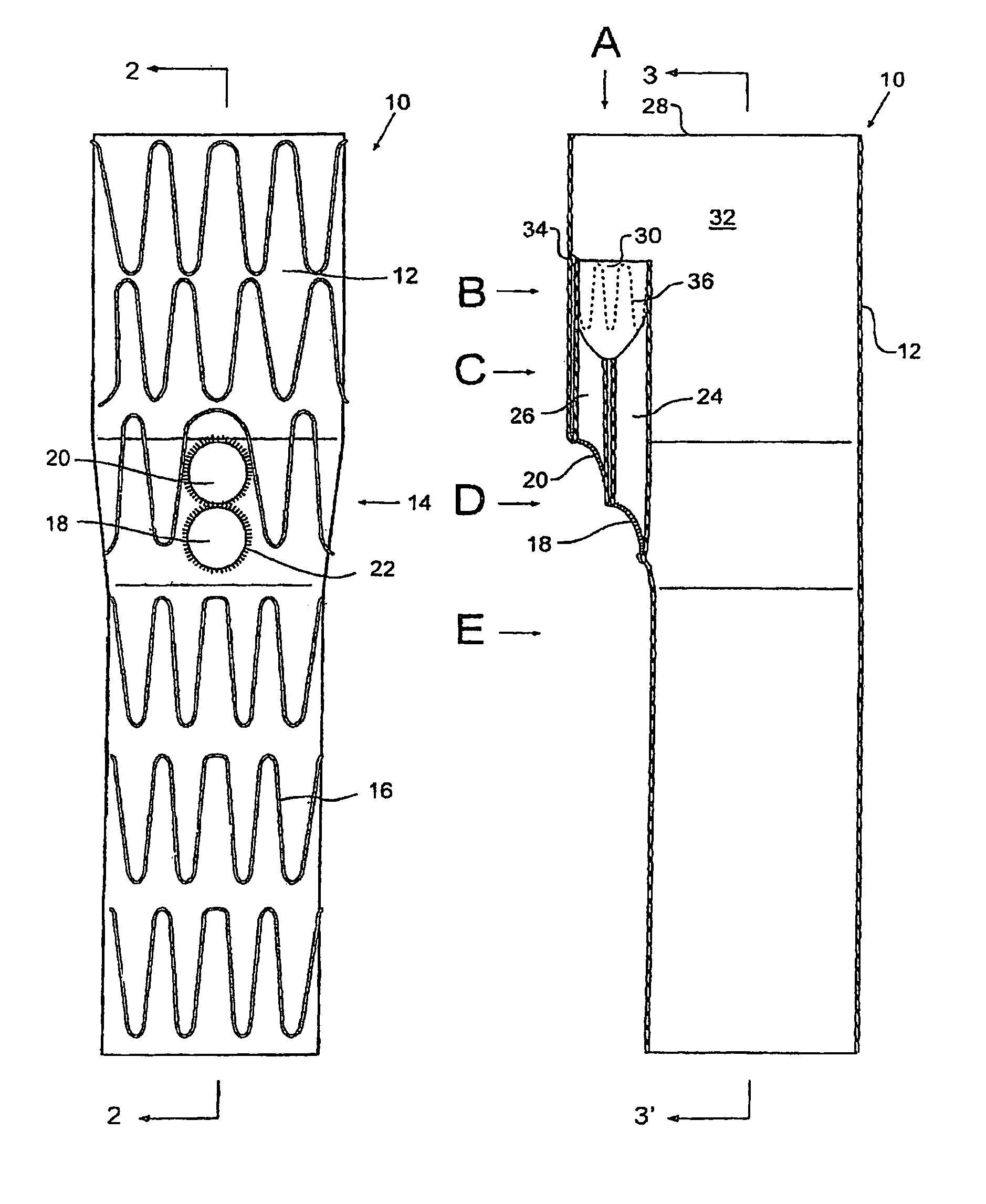
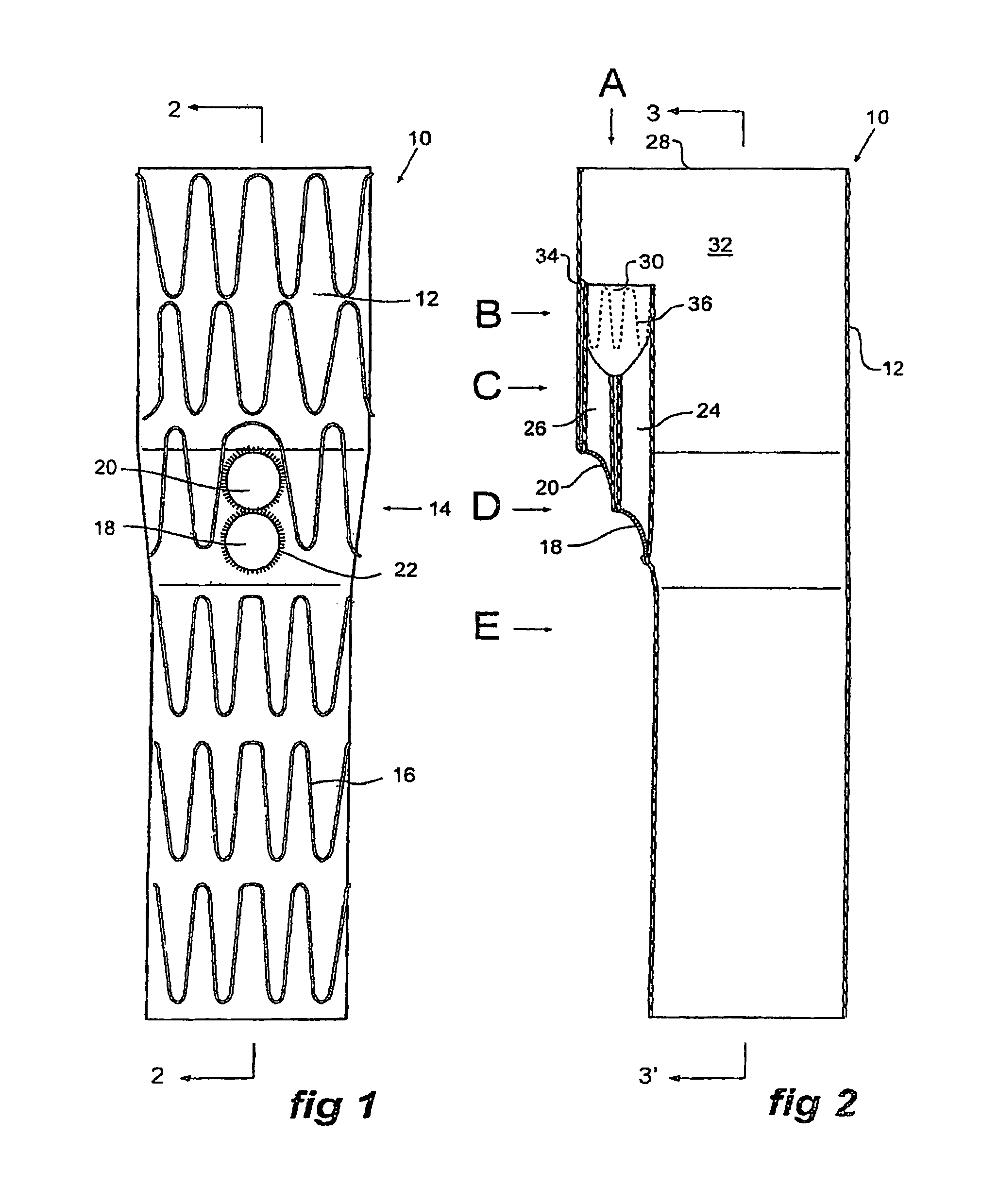
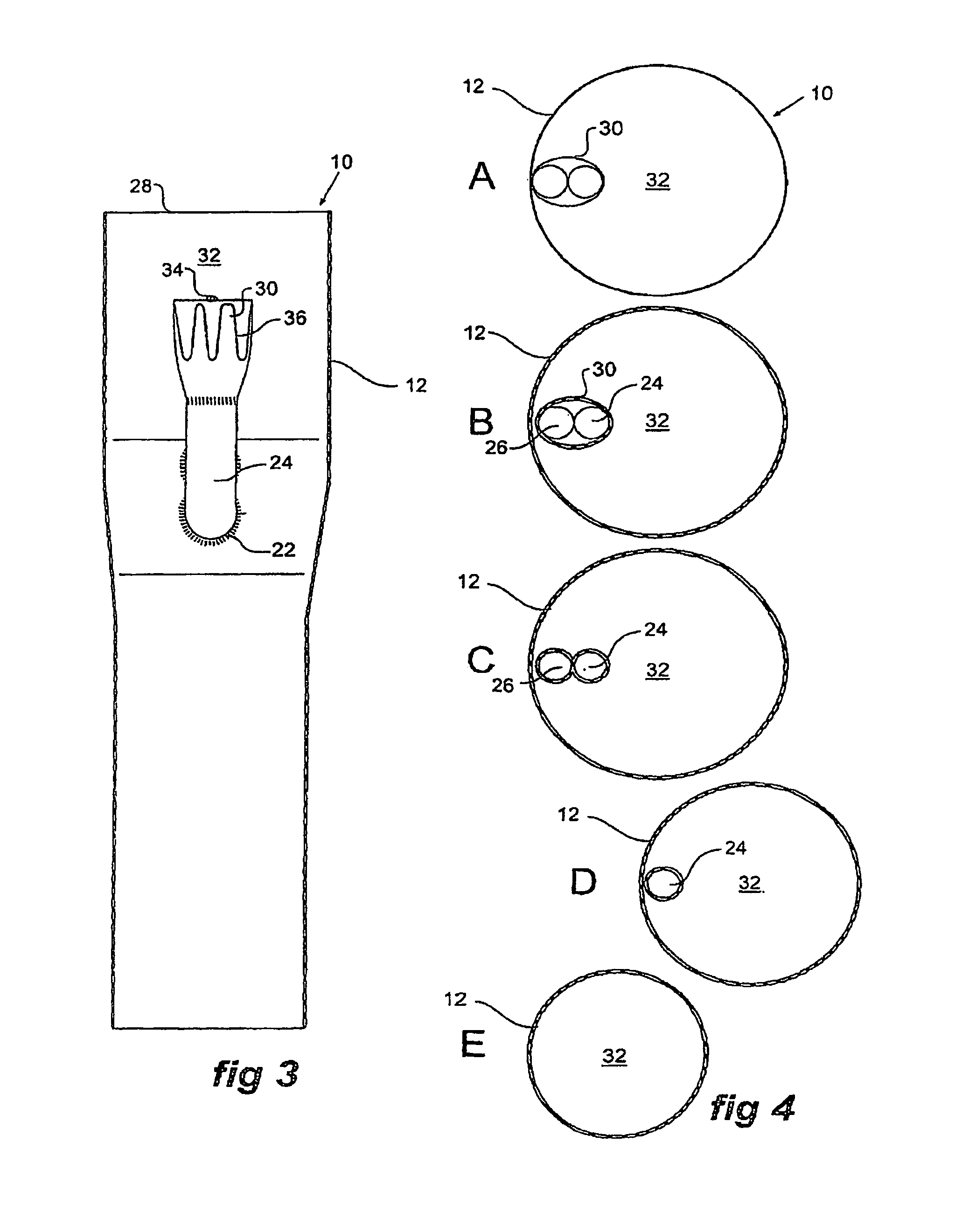
[0029]Looking more closely at the drawings and in particular FIGS. 1 to 4 showing a first embodiment of a stent graft, it will be seen that stent graft 10 has a tubular body 12 of a biocompatible material, which includes a tapered central region 14. The tubular body is supported by stents 16. Preferably these stents are self expanding Gianturco zig-zag Z stents but other forms of stents may also be included or used.

[0030]In the tapered region 14, there are at least two fenestrations 18 and 20 defined by a resilient nitinol wire 22 around the periphery of the fenestration.

[0031]As can be seen in FIG. 2, there are a pair of tubes 24 and 26 extending up from the fenestrations 18 and 20 towards the proximal end 28 of the stent graft 10 and these tubes 24 and 26 open into a single larger tube 30 which opens into the lumen 32 of the stent graft 10. The larger tube 30 is connected by stitching 34 to the tubular body 24 and a zig-zag self-expanding stent 36 is deployed around the outside of...


PUM


Abstract

A stent graft (10; 40; 80) has a tubular body (12; 42; 82) of a biocompatible material and at least two fenestrations (18, 20; 48, 50; 84, 86, 88). The at least two fenestrations (10, 20; 48, 50; 84, 86, 88) are adjacent each other and each has a tube {24, 26; 54, 55; 90, 92, 94) extending into the tubular body (1 2; 42; 82). The tubes (24, 26; 54, 55; 90, 92, 94) are joined inside the tubular body (12; 42; 82) into a single larger tube (30; 60; 96) to facilitate catheterization.

Description

RELATED APPLICATIONS[0001]The present patent document is a §371 filing based on PCT Application Serial No. PCT / US2007 / 018410, filed Aug. 20, 2007 (and published as WO 2008 / 021557 A1 on Feb. 21, 2008), designating the United States and published in English, which claims the benefit of the filing date under 35 U.S.C. §119(e) of Provisional U.S. Patent Application Ser. No. 60 / 838,776, filed Aug. 18, 2006. All of the foregoing applications are hereby incorporated by reference in their entirety.TECHNICAL FIELD[0002]This invention relates to a medical device and more particularly to a stent graft for endovascular deployment. In particular, the invention relates to the configuration of branched stent grafts.BACKGROUND OF THE INVENTION[0003]Stent grafts have been devised for endovascular deployment to bypass a diseased portion of a vessel and such stent grafts can be deployed into body vessels such as the aorta. Where there are branches from the bodily vessel such as the aorta it is desirab...

Claims


Application Information

Patent Timeline
Patent Type & Authority Patents(United States)
IPC IPC(8): A61F2/06
CPCA61F2/07A61F2002/061A61F2220/0075A61F2/89A61F2002/075A61F2250/0039
Inventor HARTLEY, DAVID E.CHUTER, TIMOTHY A. M.
Owner WILLIAM A COOK AUSTRALIA
Why Eureka
Try Eureka