Collecting chamber for a vacuum cleaner

a vacuum cleaner and collection chamber technology, which is applied in the direction of filter regeneration, dispersed particle filtration, and using liquid separation agents, can solve the problems of reducing the separation inhibiting efficient emptying and cleaning of the collection chamber, and affecting the efficiency of the vacuum cleaner. achieve the effect of convenient emptying of the chamber

Inactive Publication Date: 2011-09-20
DYSON TECH LTD
View PDF16 Cites 95 Cited by
  • Summary
  • Abstract
  • Description
  • Claims
  • Application Information

AI Technical Summary

Benefits of technology

[0009]The provision of a dividing wall that does not have a constant separation with respect to the base permits a wall having a region of greater separation from the base to be employed, which facilitates emptying of the chamber.

Problems solved by technology

While bagless vacuum cleaners are successful in maintaining a consistently high level of suction, the absence of a bag can make it difficult to dispose of the dirt and dust which is collected by the cleaner.
Without a reliable seal, air and dust will escape from the chamber and the separation efficiency of the vacuum cleaner will be reduced.
A problem which may be encountered with such vacuum cleaners is that the wall dividing the dust collection chamber into different collection regions typically occupies a relatively large volume within the dust collection chamber and so may inhibit efficient emptying and cleaning of the collection chamber.

Method used


Image

  • Collecting chamber for a vacuum cleaner
  • Collecting chamber for a vacuum cleaner
  • Collecting chamber for a vacuum cleaner

Examples


Embodiment Construction

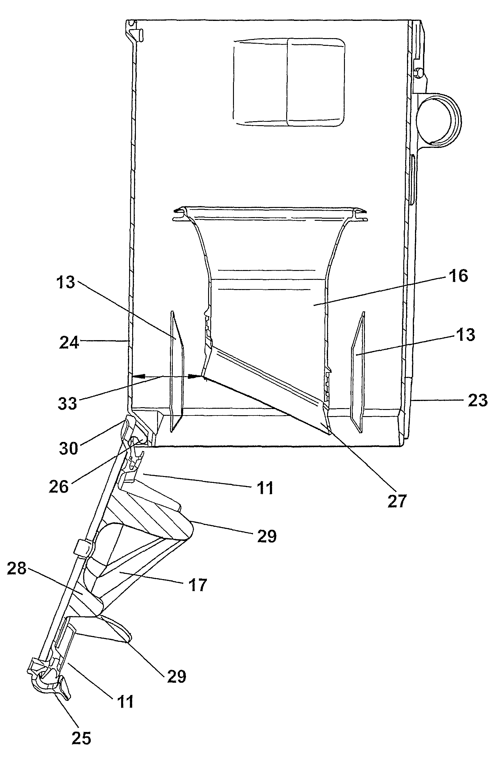
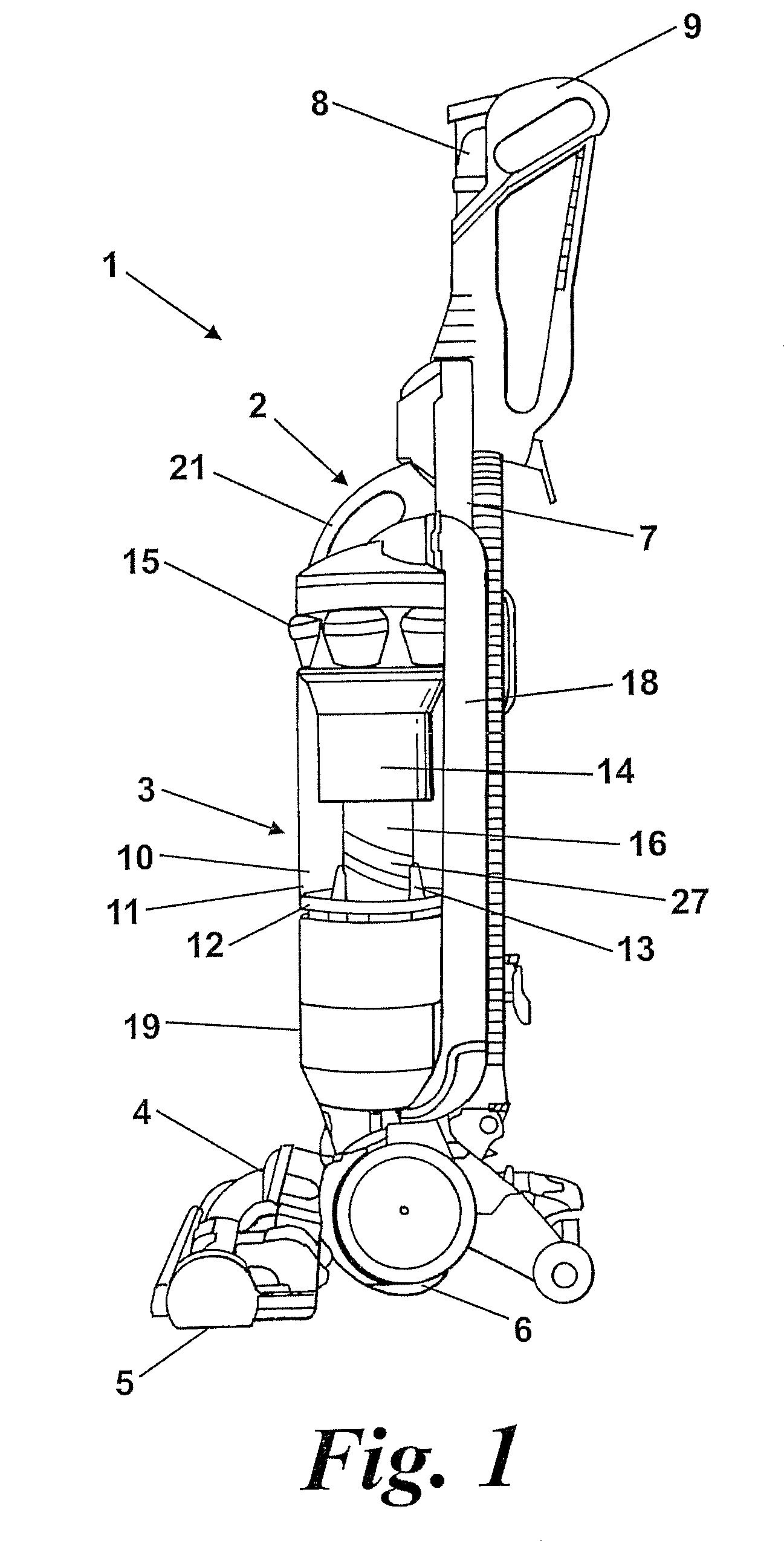
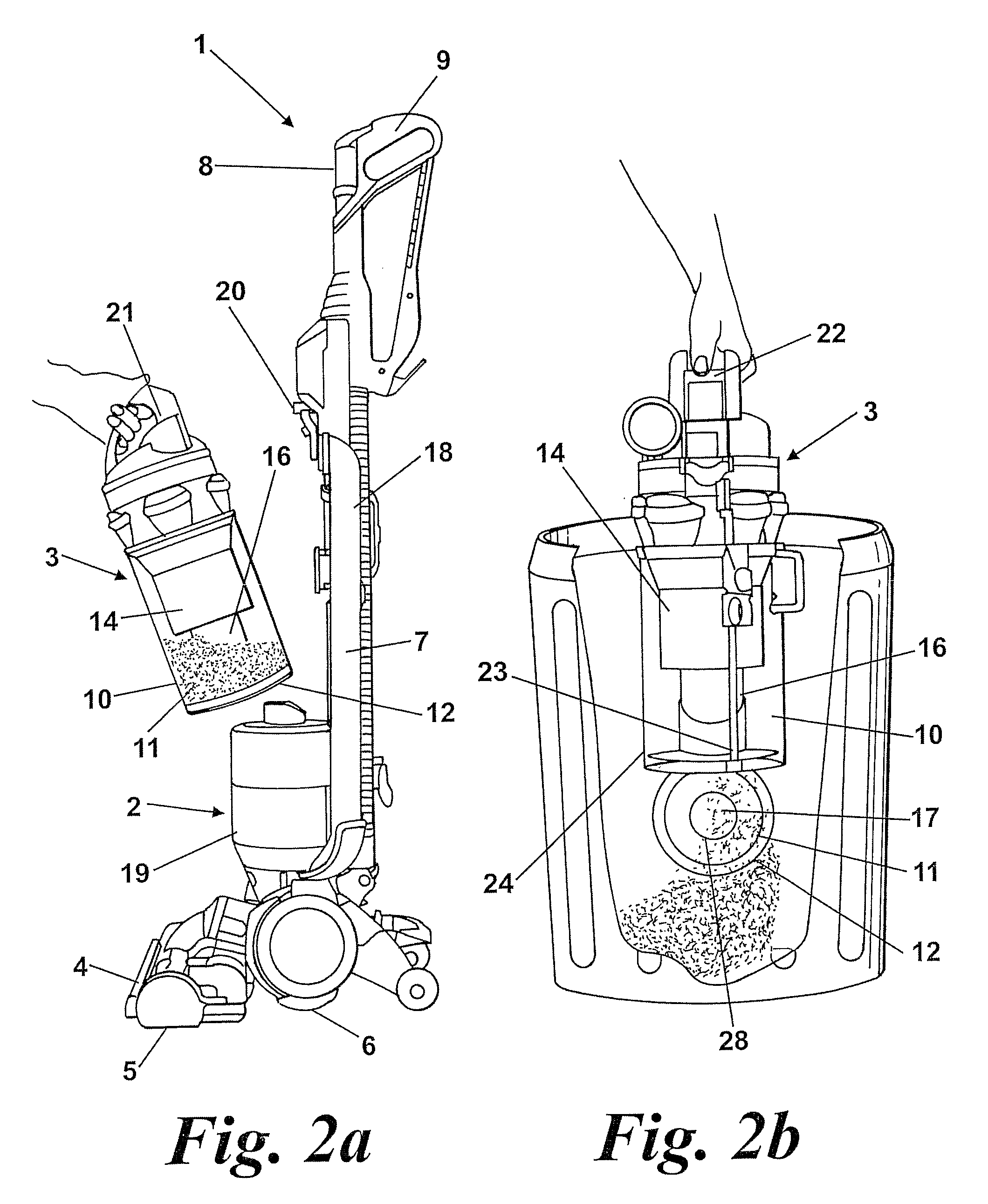
[0026]With reference to FIGS. 1 to 4, a vacuum cleaner, indicated generally by the reference numeral 1, has a main chassis 2 which supports dirt and dust separation apparatus 3. The lower part of the cleaner 1 comprises a cleaner head 4 for engaging with the floor surface. The cleaner head 4 has a downwardly facing suction inlet 5. A brush bar (not visible in these drawings) is mounted in the mouth of the inlet 5 for agitating a floor surface during a cleaning operation. The cleaner head 4 is pivotably mounted to the main chassis 2, and a rolling support assembly 6 is provided for supporting the cleaner 1 and allowing movement across a floor surface. A spine 7 of the chassis 2 extends upwardly and provides support for the components of the cleaner 1. A cleaning wand 8 is provided to allow a user to carry out above-the-floor cleaning and cleaning in places which are inaccessible by the main cleaning head 4. When the wand 8 is fixed to the spine 7, the wand forms the handle of the cle...


PUM

PropertyMeasurementUnit
distancesaaaaaaaaaa
angleaaaaaaaaaa
flexibleaaaaaaaaaa

Abstract

A bagless vacuum cleaner includes a separating unit for separating dirt and dust from a dirt-laden airflow which is drawn in by the cleaner. The separating unit has a chamber with collection areas for collecting dirt and dust which is separated from the airflow. A base of the separating unit is movable between a closed position and an open position. A dividing wall between the collection areas is arranged so that its end is spaced from the base by different distances at different respective regions. This enables an enlarged opening, by which dirt and dust can be emptied from the chamber, to be provided, which facilitates emptying of the chamber.

Description

REFERENCE TO RELATED APPLICATIONS[0001]This application is a national stage application under 35 USC 371 of International Application No. PCT / GB2007 / 003207, filed Aug. 23, 2007, which claims the priority of United Kingdom Application No. 0617181.3, filed Sep. 1, 2006, the contents of which prior applications are incorporated herein by reference.FIELD OF THE INVENTION[0002]This invention relates to a collecting chamber for a bagless vacuum cleaner and to a vacuum cleaner which incorporates the collecting chamber.BACKGROUND OF THE INVENTION[0003]Vacuum cleaners which separate dirt and dust from an airflow without the use of a filter bag, so-called bagless vacuum cleaners, are becoming increasingly popular. Most bagless cleaners use cyclonic or centrifugal separation to spin dirt and dust from the airflow. By avoiding the use of a filter bag as the primary form of separation, it has been found possible to maintain a consistently high level of suction, even as the collecting chamber fil...

Claims


Application Information

Patent Timeline
Patent Type & Authority Patents(United States)
IPC IPC(8): A47L5/36
CPCA47L9/1625A47L9/1641A47L9/1683Y10S55/03A47L9/1608B04C5/185B04C5/26
Inventor HOWES, GORDON JAMES
Owner DYSON TECH LTD
Why Eureka
Try Eureka