Apparatus for installation of electrical floor boxes

a technology for floor boxes and electrical equipment, applied in the direction of electrical apparatus casings/cabinets/drawers, coupling device connections, insulated conductors, etc., can solve the problems of increasing the time for completion of a job, forming such a hole in an existing concrete floor for installing a floor box, and affecting the installation of the floor box into an existing board-on-joist floor, so as to reduce the installation time and inventory

Active Publication Date: 2011-09-20
THE WIREMOLD CO
View PDF5 Cites 10 Cited by
  • Summary
  • Abstract
  • Description
  • Claims
  • Application Information

AI Technical Summary

Benefits of technology

[0035]One advantage of the present invention is that the clamp device 14 can be used for installing an electrical floor box 12 either in a raised floor structure (FIG. 1) or in a concrete floor (FIG. 7). Thus, the present invention enables electrical contractors to purchase fewer parts for all installations and keep at hand only one component for accomplishing various installations. This advantage reduces installation time and inventory.
[0036]Another advantage of the present invention is that the clamp device can be used to fasten the floor box to a floor without making additional holes for fasteners.

Problems solved by technology

If the electrician has the wrong equipment for installation of the box, the electrician may need to leave the construction site to obtain the proper installation devices, thereby resulting in added time for completion of a job.
Forming such a hole in an existing concrete floor for installing a floor box can be expensive, dirty, and disruptive to other uses of the area surrounding the intended in-floor box location.
However, actually installing a floor box into an existing board-on-joist floor can be challenging.
In particular, firmly fastening the box to the floor can be difficult because many flooring materials do not accept or retain conventional fasteners, or may interfere with penetration of fasteners into the sub-floor or joists.
In particular, stone or ceramic tiles and some types of wood-finish resin laminates can frustrate most desirable methods of fastening a floor box in the floor.
Ceramics are particularly frustrating because incautious fastening efforts can destroy the tile flooring.
Fastening the floor box to the floor structure is further made more difficult by a desire to minimize secondary cuts or holes drilled in the flooring material, since each additional cut or hole further weakens and detracts from the appearance of the flooring material.

Method used


Image

  • Apparatus for installation of electrical floor boxes
  • Apparatus for installation of electrical floor boxes
  • Apparatus for installation of electrical floor boxes

Examples


Embodiment Construction

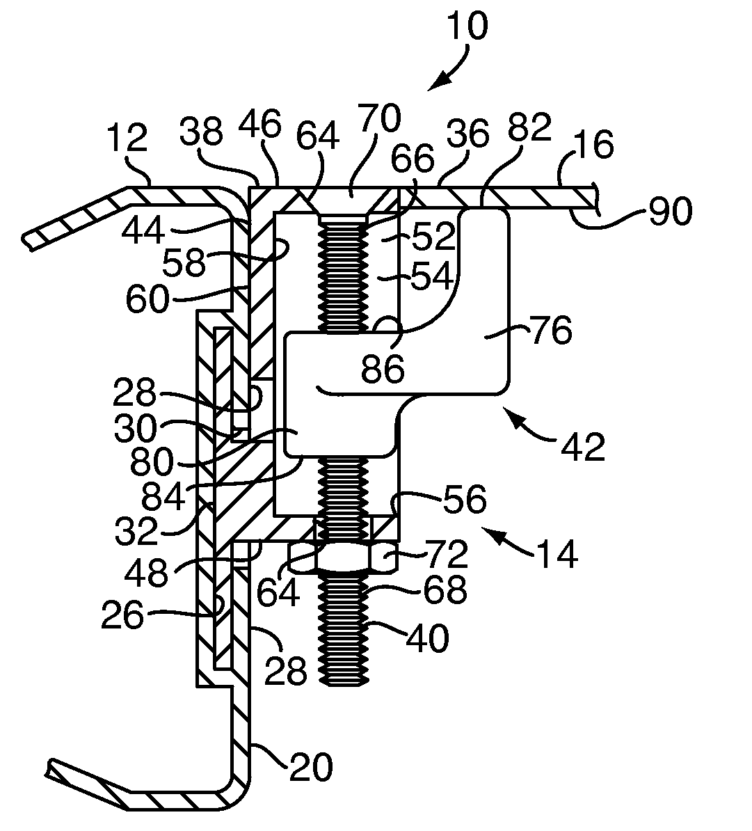
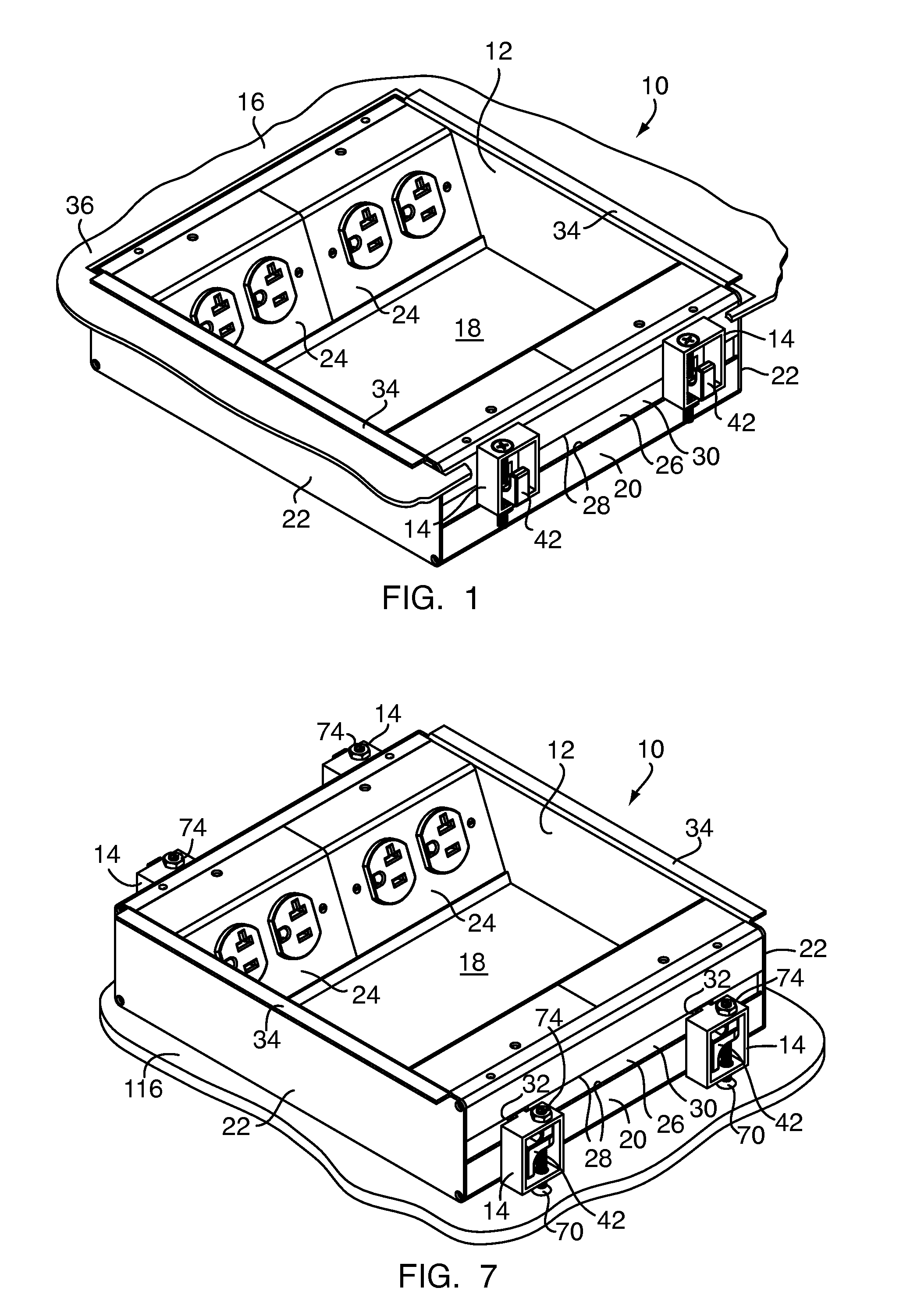
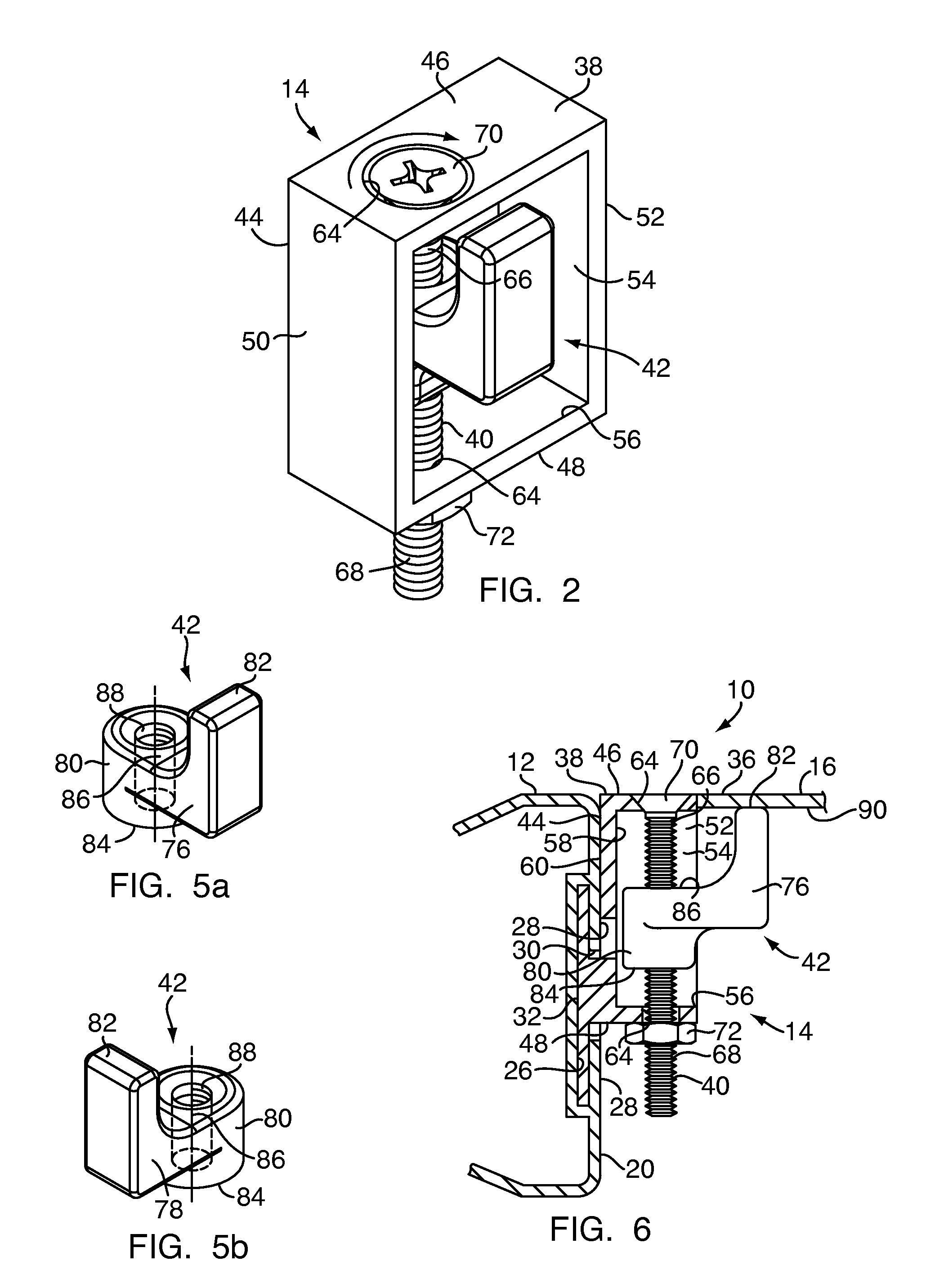
[0019]FIGS. 1 and 7 illustrate an electrical floor box assembly 10 in accordance with the present invention. The electrical floor box assembly 10 includes an electrical floor box 12 and a plurality of clamp devices 14 attached to the box 12 for securing the box to a floor structure 16 (FIG. 1) or for leveling the box on a support surface 116 (FIG. 7). In each mounting method, at least one clamp device 14 is used to secure and locate the box 12 in a desirable position and fit with respect to the upper surface of the floor 16, as described in more detail below, regardless of whether the box 12 is intended to be clamped beneath the floor surface or leveled on the support surface.

[0020]As shown in FIG. 1, the floor box 12 has a general box-like shape constructed from a bottom wall 18, generally opposed grooved sidewalls 20, and generally opposed flanged sidewalls 22, collectively defining an interior cavity of the box 12 which houses wiring components, such as electrical outlets, genera...


PUM


Abstract

An electrical floor box assembly for installation in a floor structure includes an electrical floor box having a plurality of sidewalls and at least one clamp device attached to a sidewall so that the floor box may be mounted to a raised floor structure or leveled atop a support surface using the clamp device. The clamp device includes a clamp body, a threaded rod mounted for rotation along a longitudinal axis within the clamp body, and a clamp arm threadingly engaging the threaded rod so that it is movable along the rod in association with rotation thereof and can be moved into engagement with the undersurface of the floor structure to secure the floor box in place. The clamp device may further include a leveling subassembly for installation of the electrical floor box onto a support surface prior to construction of the floor around the leveled floor box.

Description

CROSS REFERENCE TO RELATED APPLICATIONS[0001]The present application claims priority to U.S. Provisional Application Ser. No. 61 / 033,192, filed Mar. 3, 2008, and hereby incorporates herein by reference the disclosures thereof.FIELD OF THE INVENTION[0002]The present invention generally relates to electrical floor boxes and, more particularly, to apparatus for installation thereof.BACKGROUND[0003]Electrical floor boxes are typically installed in a floor to house electrical components and provide a connection to electrical, communication and other wiring routed under and through the floor of a building structure. Such floor boxes generally must be mounted substantially flush with the upper surface of the floor. Various buildings have floors of different types, materials and thickness. For example, electrical floor boxes may be installed in a concrete floor, such as in an exhibition center, arena or office building, or in a joisted or raised floor, such as in a house. Some construction ...

Claims


Application Information

Patent Timeline
Patent Type & Authority Patents(United States)
IPC IPC(8): H02G3/08
CPCH02G3/185
Inventor THIBAULT, STEVEN C.
Owner THE WIREMOLD CO
Why Eureka
Try Eureka