Filament winding apparatus, filament winding design method, and manufacturing method of tank

a technology of winding apparatus and filament, which is applied in mechanical apparatus, vessel construction details, transportation and packaging, etc., can solve the problems of not achieving the intended winding, and achieve the effect of reducing the manufacturing time of the tank, reducing the manufacturing cost, and increasing the thickness of the reinforcing layer

Active Publication Date: 2019-11-14
TOYOTA JIDOSHA KK
View PDF0 Cites 3 Cited by
  • Summary
  • Abstract
  • Description
  • Claims
  • Application Information

AI Technical Summary

Benefits of technology

[0008](3) In the filament winding apparatus of the above aspect, the liner may include: a cylindrical section; and two ends that close both of longitudinal ends of the cylindrical section. When a rate of an area of the cylindrical section covered by one of the bundles of fibers with respect to a surface area of the cylindrical section is referred to as a coverage rate of the one bundle of fibers, a sum of the coverage rates of the N bundles of fibers may be set within a range that is equal to or larger than 75% and smaller than 100%. According to the filament winding apparatus of this aspect, the bundles of fibers supplied from the different guide members can slightly overlap each other in the cylindrical section. In this way, a thickness of the reinforcing layer can be increased without increasing feeding amounts of the bundles of fibers.
[0009](4) In the filament winding apparatus of the above aspect, N indicating the number of the guide members may be any one of integers equal to or larger than two and equal to or smaller than nine. According to the filament winding apparatus of this aspect, an installation time of the guide members and a winding time of the bundles of fibers can be secured in a well-balanced manner, and a manufacturing time of a tank can be shortened.
[0010](5) In the filament winding apparatus of the above aspect, N indicating the number of the guide members may be any one of integers equal to or larger than two and equal to or smaller than four. According to the filament winding apparatus of this aspect, the installation time of the guide members is not excessively increased, and the manufacturing time of the tank can be shortened.
[0011](6) In the filament winding apparatus of the above aspect, the drive unit may cause the N guide members to move in tune of each other. According to the filament winding apparatus of this aspect, control to cause movement of the plural guide members can easily be executed.
[0012](7) In the filament winding apparatus of the above aspect, the relative angle θgM of each of the N guide members may satisfy 0°≤θgM<180°. According to the filament winding apparatus of this aspect, the liner can easily be brought in and out.

Problems solved by technology

However, the inventor of the disclosure has found that, in the case where the bundles of fibers are supplied from the plural guide members and are wound helically around the liner, there is a possibility that intended winding is not achieved.

Method used


Image

  • Filament winding apparatus, filament winding design method, and manufacturing method of tank
  • Filament winding apparatus, filament winding design method, and manufacturing method of tank
  • Filament winding apparatus, filament winding design method, and manufacturing method of tank

Examples


first other embodiment

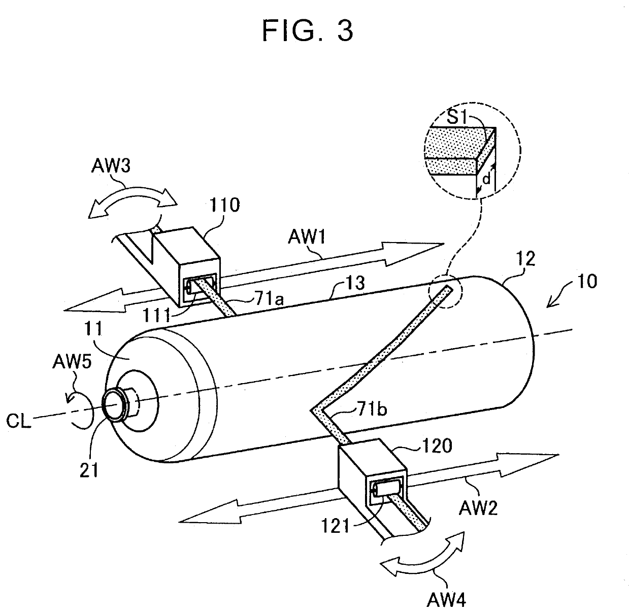
[0057]In the embodiment that has been described above, the guide members 110, 120 are arranged at the equally-spaced intervals around the liner 10 with the center axis CL of the liner 10 being the center. However, the guide members 110, 120 may be arranged at unequally-spaced intervals around the liner 10. However, in the case where the guide members 110, 120 are arranged at the equally-spaced intervals around the liner 10 with the center axis CL of the liner 10 being the center, a winding speed of each of the bundles of fibers 71a, 71b can be increased. In addition, the relative angle θgM of each of the guide members 110, 120 may be set to satisfy 0°≤θgM110 is set at 0°, the relative angle θgM of the second guide member 120 may be set at 90°. In such a case, the guide members 110, 120 are arranged around the liner 10 in such a manner as not to be excessively diverged. As a result, the liner 10 can easily be brought in and out.

second other embodiment

[0058]In the embodiment that has been described above, the drive units 410, 420 cause the two guide members 110, 120 to move in tune of each other. However, the drive units 410, 420 may cause the two guide members 110, 120 to move separately to wind the bundles of fibers 71a, 71b. However, in the case where the two guide members 110, 120 move in tune of each other, the bundles of fibers 71a, 71b can be wound by the simple control.

third other embodiment

[0059]As the appropriate number of winding W, with which the assumed positions m of the bundles of fibers supplied from the guide members match the actual positions n at the time when the bundles of fibers are wound around the liner 10 by using the three guide members, 14 is used. Such an example will be described below. When the number N of the guide members is set to 3, and the number of winding W is set to 14, the following calculation result the assumed positions m and the actual positions n is obtained. Here, the relative angle θgM of the guide member with the number M being 1 is set at 0°, the relative angle θgM of the guide member with the number M being 2 is set at 120°, and the relative angle θgM of the guide member with the number M being 3 is set at 240°.

Result (5) The guide member: number M=1, the relative angle θgM=0°

[0060]The bundle of fibers: the assumed position m=0, the actual position n=0

[0061]The guide member: number M=2, the relative angle θgM=120°

[0062]The bundl...


PUM

PropertyMeasurementUnit
relative angleaaaaaaaaaa
relative angle θgMaaaaaaaaaa
winding angleaaaaaaaaaa

Abstract

A filament winding apparatus includes: N guide members arranged around a liner having an elongate shape such that the N guide members are centered around a center axis of the liner, the center axis extending in a longitudinal direction of the liner, each of the N guide members being configured to supply one bundle of fibers, and N being an integer equal to or larger than two, a drive unit configured to repeat, W times, a winding operation to helically wind N bundles of fibers supplied respectively from the N guide members around the liner at the same winding angle to form a reinforcing layer, the winding operation being an operation in which each of the N guide members travels, in a direction parallel to the center axis of the liner, from and back to a winding start position, and W being an integer equal to or larger than two.

Description

INCORPORATION BY REFERENCE[0001]The disclosure of Japanese Patent Application No. 2018-091274 filed on May 10, 2018 including the specification, drawings and abstract is incorporated herein by reference in its entirety.BACKGROUND1. Technical Field[0002]The disclosure relates to a filament winding apparatus, a filament winding design method, and a manufacturing method of a tank accommodating a fluid.2. Description of Related Art[0003]A filament winding apparatus disclosed in Japanese Patent Application Publication No. 2005-154908 (JP 2005-154908 A) includes plural yarn-feeding units (guide members). These plural yarn-feeding units are used to wind bundles of fibers around a tank liner or the like, and are arranged at substantially equally-spaced intervals around a member around which the bundles of fibers are wound (a fiber bundle wound member) with a longitudinal axis of the member being a center.SUMMARY[0004]In the case where the bundles of fibers are wound helically around the lin...

Claims


Application Information

Patent Timeline
Patent Type & Authority Applications(United States)
IPC IPC(8): B29C70/16B65H57/14B29C53/60
CPCB29K2105/08B29C70/16F17C2209/2154B29C53/602B65H57/14B29C53/58B29C53/8008B29C53/8016B29L2031/712B29C70/32
Inventor KOBAYASHI, TOMOYOSHIHIDAKA, YUJI
Owner TOYOTA JIDOSHA KK
Why Eureka
Try Eureka