Planar antenna

a plane antenna and antenna technology, applied in the structural form of the antenna, the antenna earthing, the resonance antenna, etc., can solve the problems of low vswr, low gain, and use of two-layer configurations

Active Publication Date: 2011-09-20
SIBEAM INC
View PDF9 Cites 273 Cited by
  • Summary
  • Abstract
  • Description
  • Claims
  • Application Information

AI Technical Summary

Problems solved by technology

Referring to FIG. 1, the structure utilizes a two-layer configuration that is a drawback in terms of manufacturing.
Furthermore, the VSWR is not very low and the gain is not high.

Method used


Image

  • Planar antenna
  • Planar antenna
  • Planar antenna

Examples


Embodiment Construction

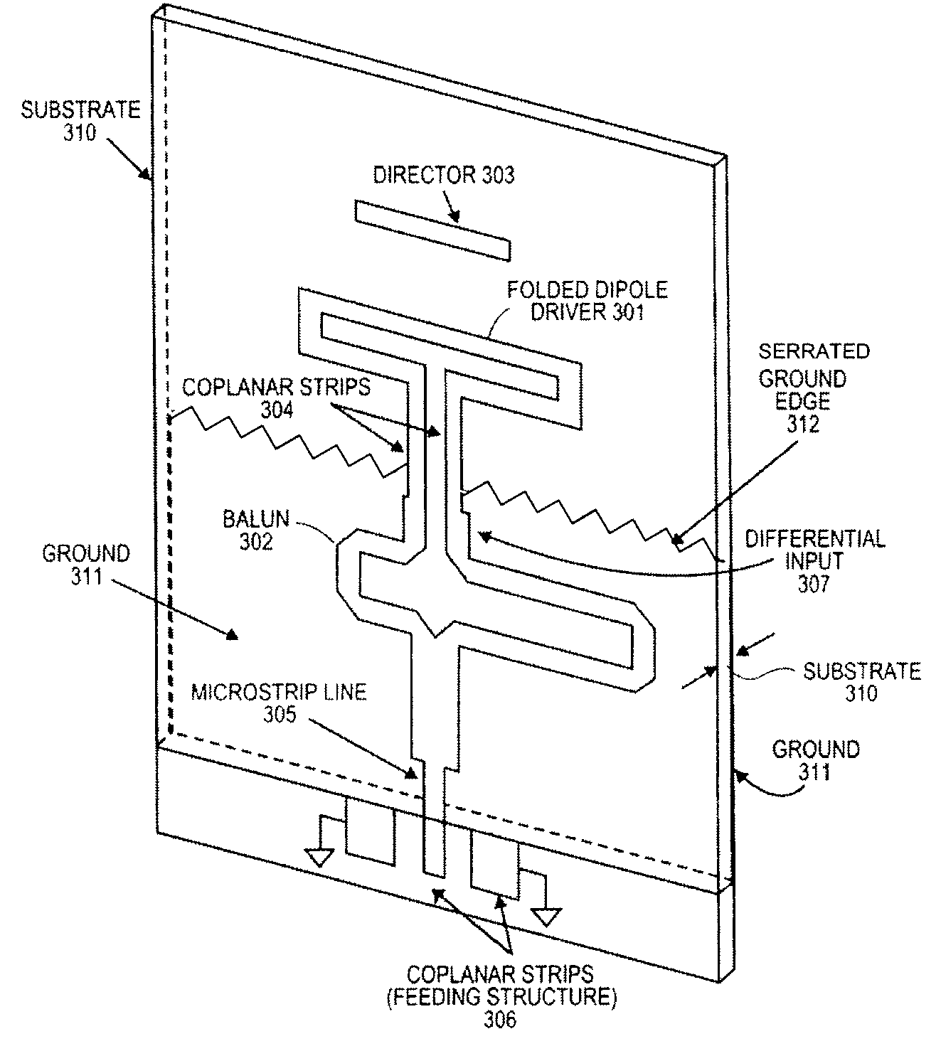
[0014]An improved compact planar radiating radio-frequency (RF) element is described. Embodiments of the planar element have broadband high performance and are useful for microwave and millimeter-wave frequencies. In one embodiment, the radiating element comprises a folded-dipole as the main driver, one or more directors, and a balanced feeding structure that is amenable to miniaturization and has a low VSWR. In one embodiment, the folded dipole is a directly fed element, i.e. driver, in a Yagi-like planar antenna.

[0015]Accordingly, embodiments of the present invention provide an improved radiating element for use as the feeding element of another antenna. The radiating element may be used in an array and may be may be fabricated using printed circuit techniques.

[0016]In the following description, numerous details are set forth to provide a more thorough explanation of the present invention. It will be apparent, however, to one skilled in the art, that the present invention may be p...


PUM


Abstract

An antenna is disclosed. In one embodiment, the antenna comprises a driver comprising a folded dipole and an integral balun coupled to the folded dipole.

Description

FIELD OF THE INVENTION[0001]The present invention relates to a device for receiving / transmitting electromagnetic waves with high efficiency and low VSWR over a broad bandwidth that can be used most particularly in the field of wireless transmissions.BACKGROUND[0002]Ever increasing use of mm-wave frequencies in communication systems, particularly those with high data rate, requires efficient antennas. Antenna directivity and radiation efficiency has to be reasonably high to overcome the high free space losses at mm-wave frequencies.[0003]Highly efficient planar radiating elements can have various applications. They can be used as the radiating elements on an array, particularly of electronically steered type. In cases where high gain radiators are required, they can be used as the feeding element of a non-array antenna such as a horn or reflector antenna to avoid considerable feed losses, e.g. such as in mm-wave. Millimeter- and submillimeter-wave devices often utilize integrated cir...

Claims


Application Information

Patent Timeline
Patent Type & Authority Patents(United States)
IPC IPC(8): H01Q1/48H01Q1/38
CPCH01Q1/38H01Q3/26H01Q9/285H01Q19/22H01Q21/062
Inventor ZARNAGHI, ROKHSAREH
Owner SIBEAM INC
Why Eureka
Try Eureka