

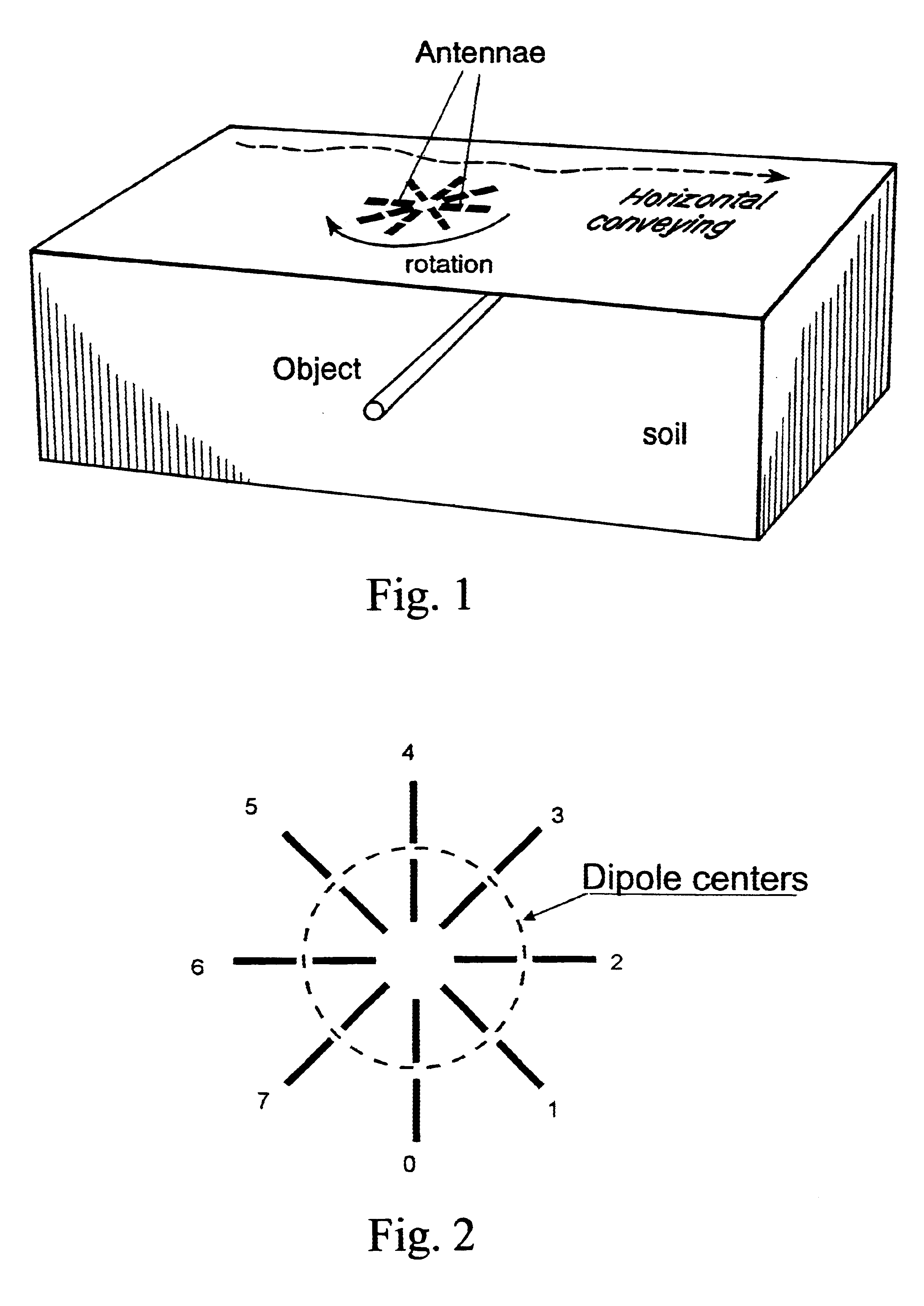
Radar plant and measurement technique for determination of the orientation and the depth of buried objects
a technology of buried objects and plant parts, applied in the direction of geological measurements, antennas, reradiation, etc., can solve the problems of inability to precisely apply mathematical equations with the preconditions mentioned, the method described for determining direction is limited to elongated objects, and the configuration is less useful for detecting objects in the ground
- Summary
- Abstract
- Description
- Claims
- Application Information
AI Technical Summary
Problems solved by technology
Method used
Image

Examples
Embodiment Construction
A reproduction of the embodiment of the invention is presented by way of example in the computer program listing appendix described above and incorporated herein by reference.
Table 1. Receiver Circuit
Description:
The receiver circuit is divided into 5 separate printed circuit boards:
Board a: LO frequency mixing.
Board b: LO signal distribution.
Board c: Receiver reference channel down conversion.
Board d Receiver test channel down conversion.
note: 2 pcs, one for each test channel
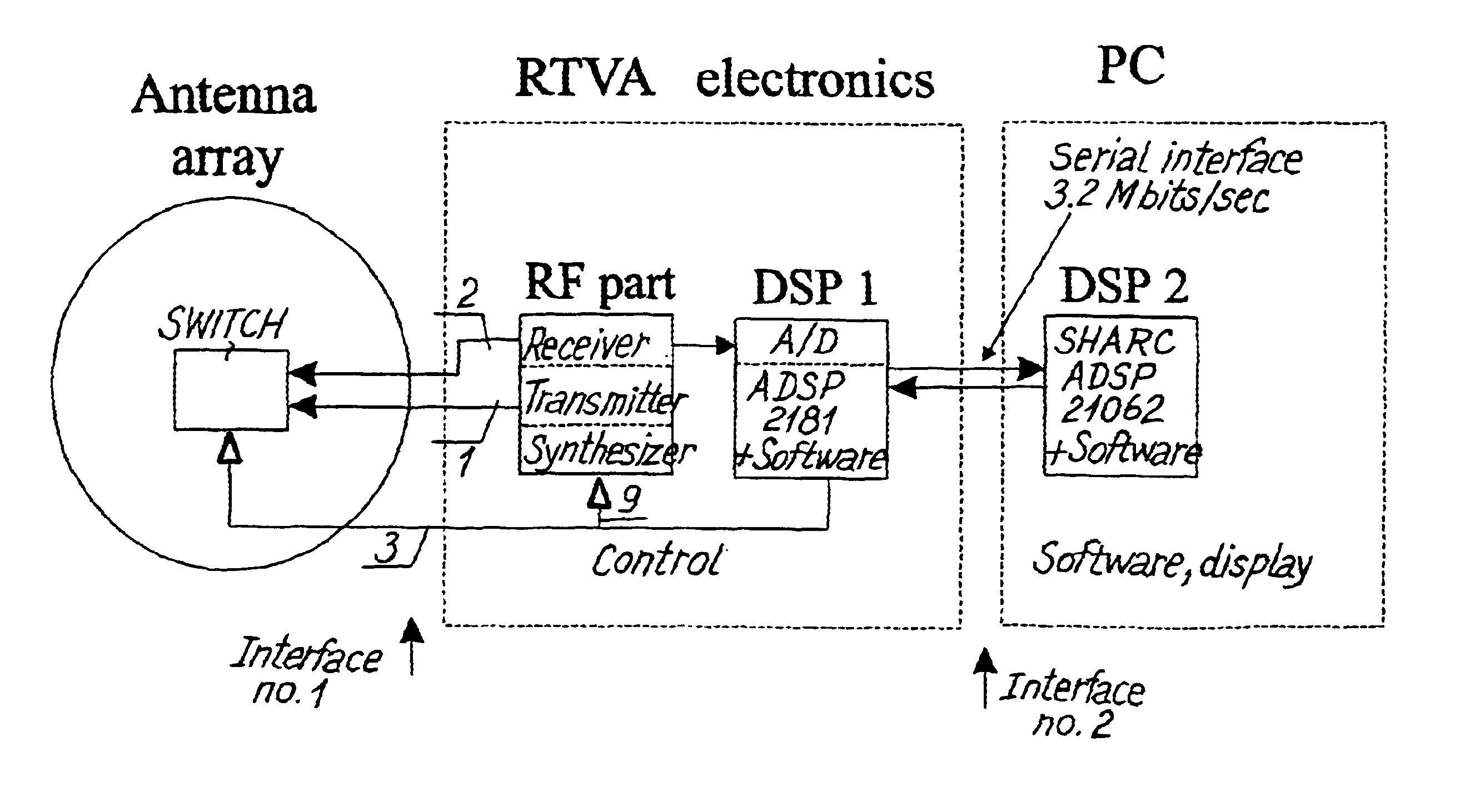
The input signals are (See receiver block diagram in FIG. 23):
B1, B2: Receiver inputs (test channels).
C: Receiver reference input.
E: 1600-2500 MHz signal from synthesizer.
G: 1510.1 MHz signal from synthesizer.
The output signals are:
H: 100 kHz IF-signal, reference channel.
I1, I2: 100 kHz IF-signal, test channels.
The 5 boards are mounted in a metal box with 5 separate rooms. High frequency signals are routed between boards by use of coaxial cables with SMA connectors. Power supplies and low-frequency control signa...
PUM
 Abstract
Description
Claims
Application Information