

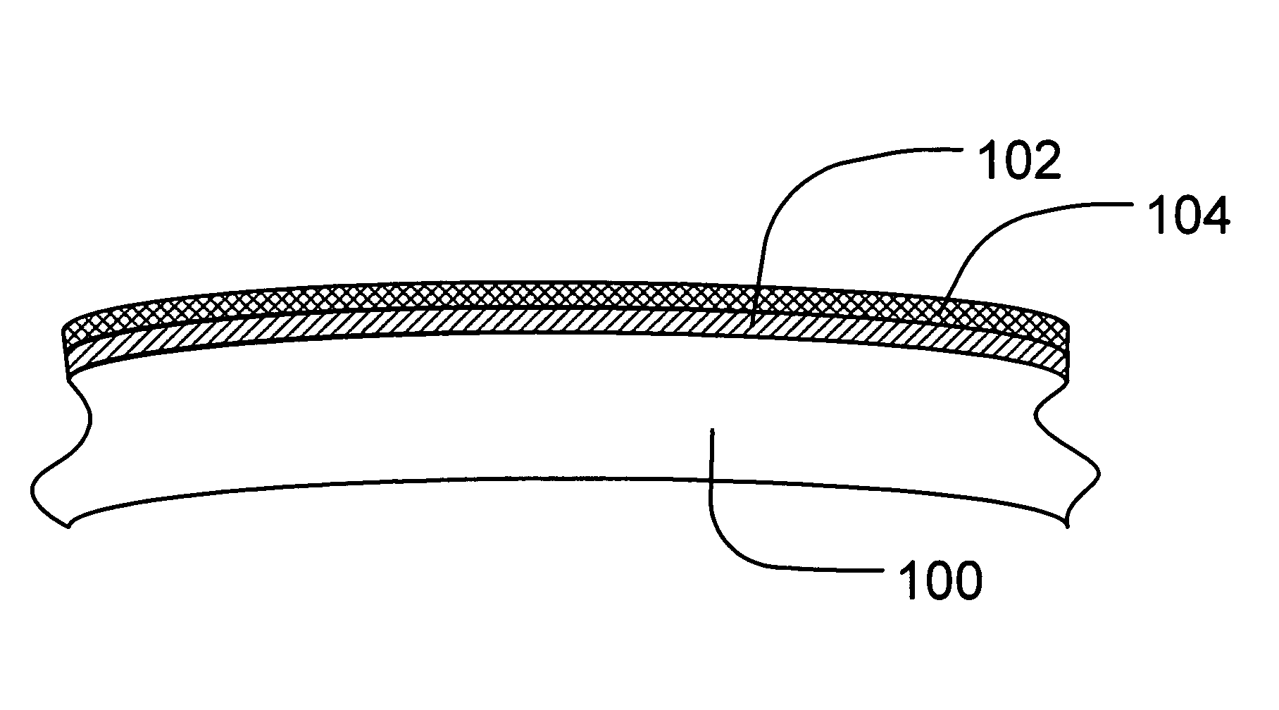
Dielectric coating for surfaces exposed to high temperature water
a technology of dielectric coating and high temperature water, which is applied in the direction of nuclear engineering, conversion screens, nuclear elements, etc., to achieve the effect of reducing or eliminating the deposition of charged particulates
- Summary
- Abstract
- Description
- Claims
- Application Information
AI Technical Summary
Benefits of technology
Problems solved by technology
Method used
Image

Examples
Embodiment Construction
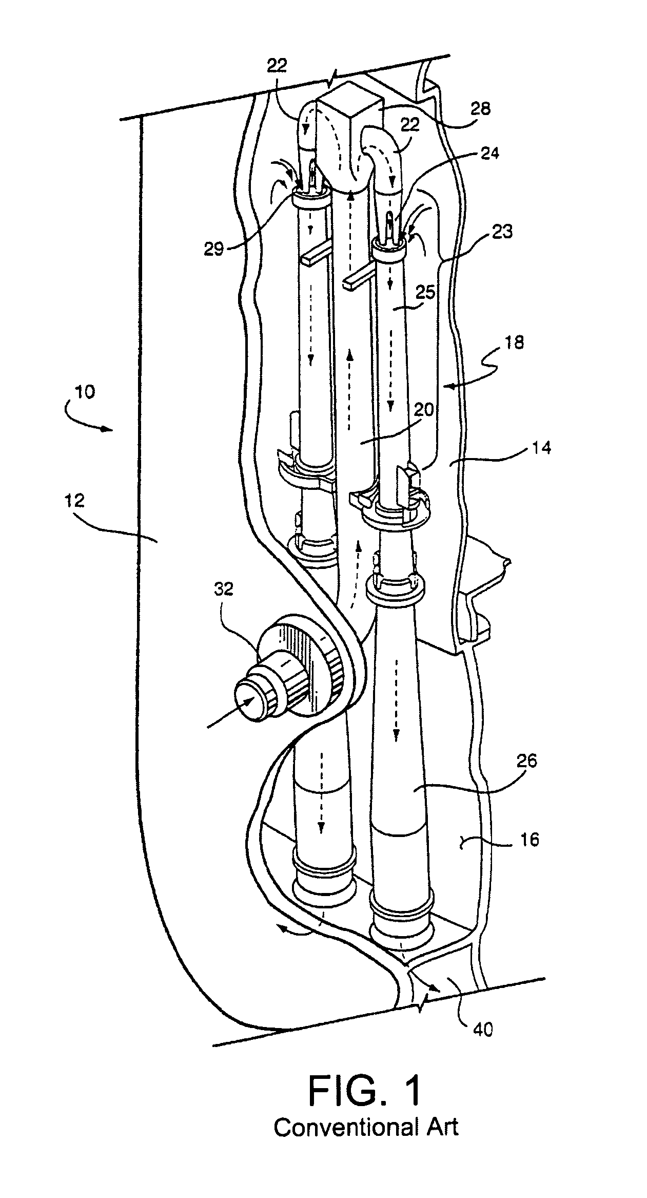
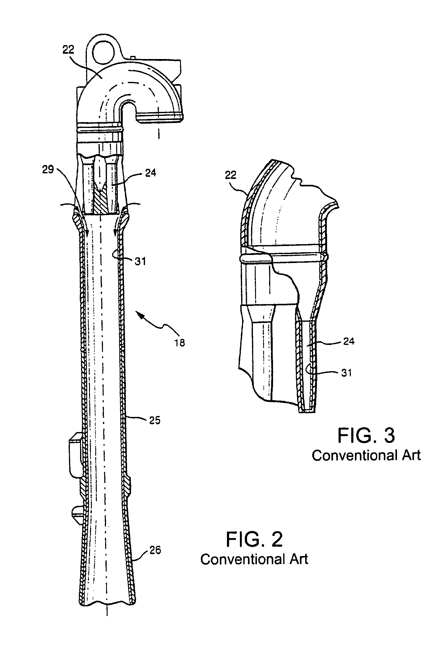
[0022]As illustrated in FIG. 1, a conventional reactor will include a reactor pressure vessel 10 that includes a reactor pressure vessel wall 12 and an inner core shroud 14 defining a generally annular space 16 therebetween that contains coolant. As in a typical BWR, a plurality of jet pumps, one being generally designated 18, are disposed at circumferential spaced positions surrounding the pressure vessel in the annular space 16 defined between the pressure vessel wall 12 and the core shroud 14. Each jet pump 18 typically comprises an inlet riser 20, a transition piece 28 adjacent the upper end of the inlet riser 20, a pair of elbows 22, inlet-mixers 23, each including nozzles 24 and mixing sections 25, and diffusers 26. Hold down assemblies adjacent the top of the jet pump 18, together with a number of braces and restraining assemblies maintain each jet pump 18 in a substantially fixed position in the annular space 16 between the core shroud 14 and pressure vessel wall 12. A therm...
PUM
| Property | Measurement | Unit |
|---|---|---|
| pressure | aaaaa | aaaaa |
| temperature | aaaaa | aaaaa |
| temperature | aaaaa | aaaaa |
Abstract
Description
Claims
Application Information