System and method for path planning

a path planning and system technology, applied in the direction of distance measurement, electric programme control, programme control, etc., can solve the problems of path planner being starved of computation, path planner being then starved of computation, and path planner not being able to run properly

Active Publication Date: 2011-09-20
INTELLIGENT PLATFORMS LLC
View PDF53 Cites 52 Cited by
  • Summary
  • Abstract
  • Description
  • Claims
  • Application Information

AI Technical Summary

Problems solved by technology

An additional task of the motion control system that requires more than 1 ms to plan a path for a sample period may starve the path planner of computation.
However, if, for example, the GPS requires more than 1 ms to calculate coordinates for a sample period, the path planner, which is required to run every 1 ms, is then starved of computation.
Thus, the path planner cannot run properly because the path planner does not have an understanding of a sample period not occurring on a 1 ms interval and the process must be aborted as the motion control system can no longer determine a proper location.

Method used


Image

  • System and method for path planning
  • System and method for path planning
  • System and method for path planning

Examples


Embodiment Construction

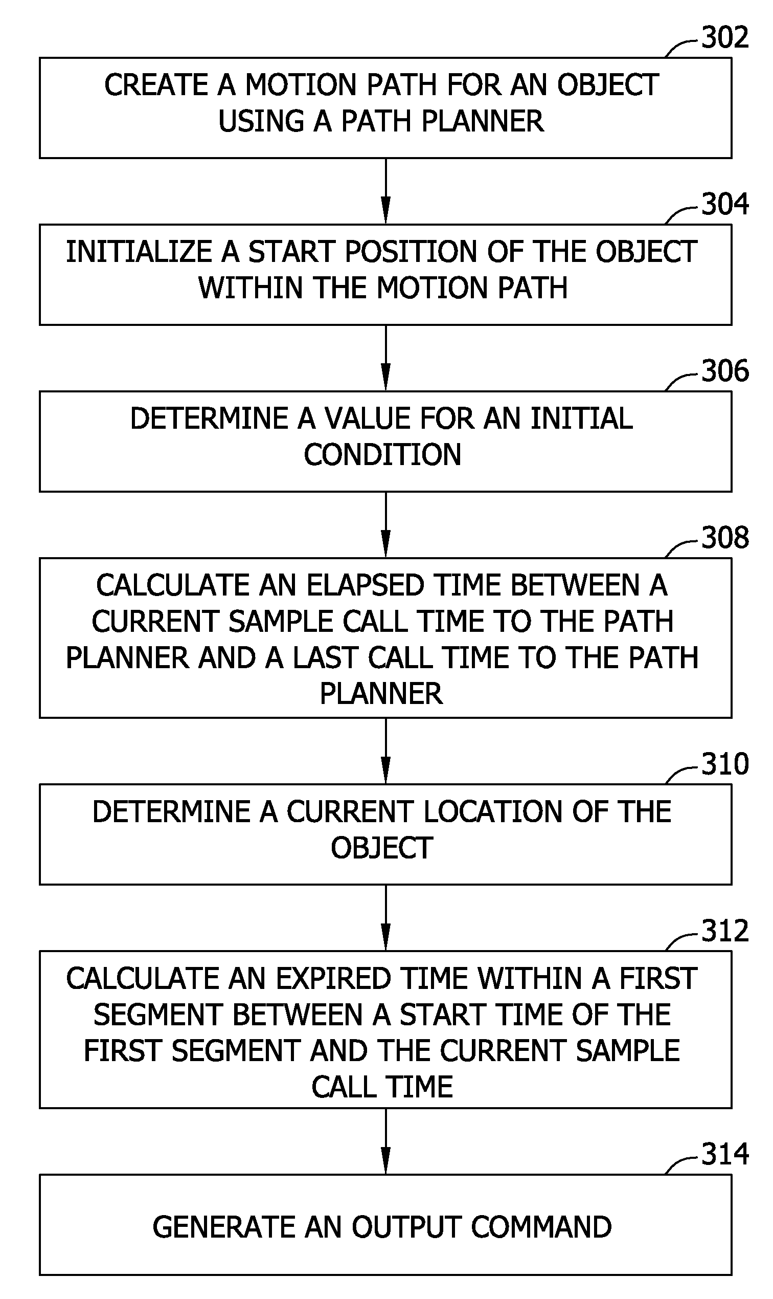
[0011]Herein described are systems and methods for mapping continuous time kinematic motion equations into a discrete time domain to yield systems and methods that provide flexibility necessary to support non-homogeneous sample periods, and further allow for discontinuities in equation sets to occur such that there is an allowance for a move to start at a user specified time that is not constrained to a multiple of sample periods.

[0012]The systems and methods for mapping continuous time kinematic motion equations into a discrete time domain described herein provide many advantages over current motion systems and methods that utilize kinematic equations for generating motion trajectories. For example, mapping continuous time kinematic motion equations into a discrete time domain does not require a fixed sample time and allows a path planner to calculate motion trajectories that do not start at a beginning of a sample period. Therefore, it is not necessary for a transition from one mo...


PUM


Abstract

A method for mapping a motion of a first object within a first motion path defined by a path planner based on a second motion path of a second object. The method includes creating the first motion path for the first object using the path planner, initializing a start position of the first object within the first motion path, determining a value for an initial condition for each segment of a plurality of segments in the first motion path created by the path planner, and calculating an elapsed time between a current sample call time to the path planner and a last sample call time to the path planner. If the calculated elapsed time is one of greater than and less than a sample period, a current location of the second object in the second motion path is determined utilizing the calculated elapsed time, an expired time within a first segment of the plurality if segments between a start time of the first segment and the current sample call time is calculated, and an output command is generated from the path planner. Execution of the generated output command alters the first motion path.

Description

BACKGROUND OF THE INVENTION[0001]The embodiments described herein relate generally to a system and method for path planning and, more particularly, to a system and method for mapping a motion of an object within a motion path defined by a path planner.[0002]Conventional motion control systems include a motion controller that provides a signal to a motor driver that activates a motor to turn. As a feedback device, a pulse encoder creates a discrete pulse for every unit of motion that occurs and transmits the pulse back to the motion controller. This is referred to as a motion event. Such conventional motion control systems accumulate motion events only over a fixed sample period. Therefore, conventional motion events are only identified as occurring over a fixed sample period.[0003]A path planner may be required to run periodically, such as every 1 millisecond (ms), in order to accumulate motion events over one or more fixed sample periods (e.g., if the motion system is accumulating ...

Claims


Application Information

Patent Timeline
Patent Type & Authority Patents(United States)
IPC IPC(8): G05B19/04G06G7/78G05D1/02G06F17/10G01C19/00G01C17/00G01C9/00G01C21/32G01C21/30G01C21/00G01C22/00G05B19/18
CPCB65C9/40G05B19/18G05B2219/42188G05B2219/42186G05B2219/25473
Inventor MILLER, DANIEL H.MORRISON, WILLIAM LINDSAY
Owner INTELLIGENT PLATFORMS LLC
Why Eureka
Try Eureka