
Cyclic steam stimulation method with multiple fractures

a cyclic steam and fracture technology, applied in the direction of fluid removal, earthwork drilling and mining, borehole/well accessories, etc., can solve the problems of large parts of the formation unheated for an extended period, uncontrollable and inefficient heating of hydrocarbon formation, and significant lowering of oil production rate of the same well

Inactive Publication Date: 2011-09-27
SHELL USA INC
View PDF14 Cites 7 Cited by
  • Summary
  • Abstract
  • Description
  • Claims
  • Application Information

AI Technical Summary

Benefits of technology

The invention is a method for producing heated hydrocarbons from a viscous hydrocarbon-containing formation using a cyclic steam stimulation process. The method involves drilling a well into the formation, cutting cavities in the formation using a rotating hydraulic jet cutting device, injecting steam into the well and cavities, and repeating this process a number of times. The method creates fractures in the formation and allows the steam to invade the formation and heat the hydrocarbons. The method can be used in heavy-oil reservoirs and can accelerate steam injection and oil production from the formation.

Problems solved by technology

A common disadvantage of the known CSS methods is that the depth of steam penetration into the formation is limited and that, if fractures are formed, their locations are difficult to control, thereby resulting in an uncontrollable and inefficient heating of the hydrocarbon formation.
Field experiences also indicate that, at most, only a couple of fractures can be created by the known method, leaving large parts of the formation unheated for an extended period.
However, the disadvantage of this method is that the oil production rate from the same well will be significantly lowered by the restricted flow through the nozzles because of the lower mobility of oil relative to the injected steam.

Method used


Image

  • Cyclic steam stimulation method with multiple fractures
  • Cyclic steam stimulation method with multiple fractures
  • Cyclic steam stimulation method with multiple fractures

Examples


Embodiment Construction

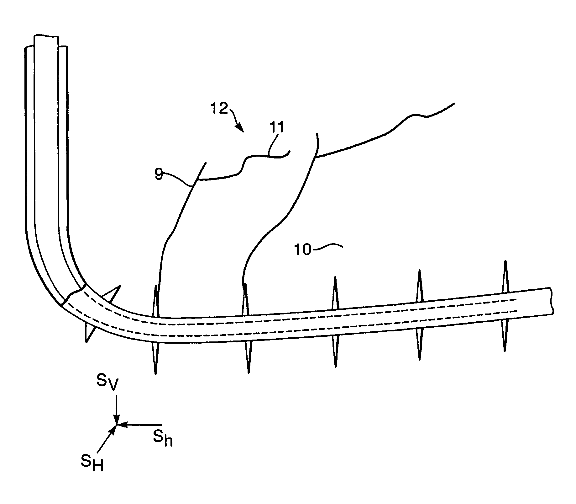
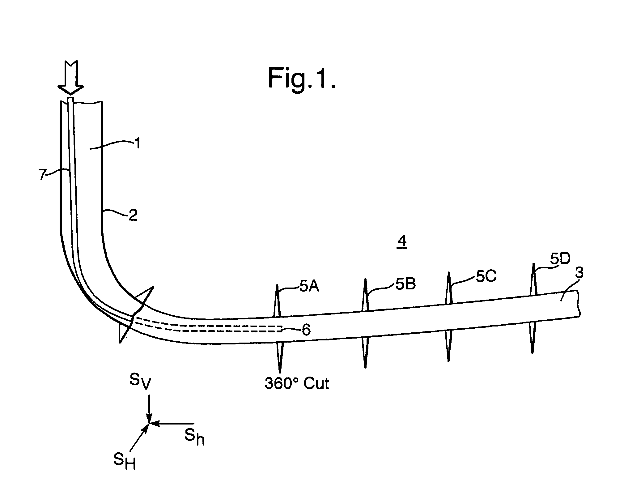
[0029]FIG. 1 shows a well 1 with a substantially vertical upper section in which a well casing 2 is arranged and a substantially horizontal lower section 3 which penetrates a viscous oil containing formation 4 in which a series of five disk-shaped cavities 5A-D are being cut by a rotating jet cutting device 6.

[0030]The jet cutting device 6 is supported and rotated by a coiled tubing or drill string assembly 7, such that the rotating jet cutting device 6 is rotated about a longitudinal axis of the wellbore over at least 360 degrees to cut the disk-shaped cavity 5A in the formation surrounding the wellbore.

[0031]FIG. 1 also shows that the formation is subject to a three dimensional combination of minimum and maximum horizontal and vertical compressive stresses Sh, SH and Sv and that the trajectory of the lower well section 3 is oriented substantially along the trajectory of minimum compressive horizontal stress Sh.

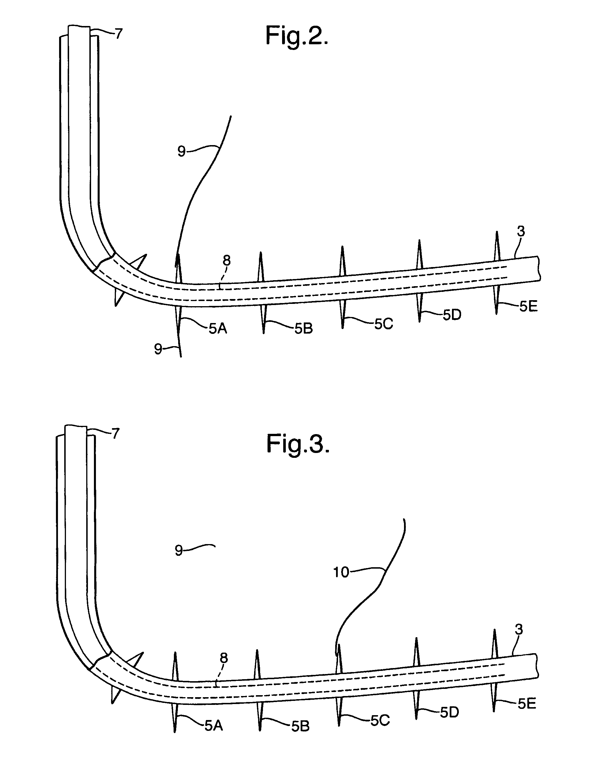
[0032]FIG. 2 shows how steam is injected through a production tubing 7,...


PUM


Abstract

A cyclic steam soak (CSS) stimulation method for producing heated hydrocarbons from a viscous hydrocarbon-containing formation comprises the steps of: a) drilling a well (1) having a substantially horizontal or inclined lower section (3) into the viscous hydrocarbon-containing formation (4) substantially along the trajectory of the minimum compressive horizontal stress Sh; b) cutting at selected intervals along the length of the lower well section (3) substantially disk-shaped cavities (5A-5D) into the viscous hydrocarbon-containing formation (4) by a rotating hydraulic jet cutting device (6); c) completing the well (1); d) injecting steam into the well (1) and disk-shaped cavities (5A-5D) at such an elevated pressure that the hydraulic pressure in at least one disk-shaped cavity 5A is above the formation fracturing pressure, thereby fracturing the formation (4) and permitting the steam to invade the formation surrounding the fracture and to heat hydrocarbons in the steam invaded zone; e) interrupting steam injection and producing heated hydrocarbons via the well (1); and f) repeating steps (d) and (e) a number of times.

Description

PRIORITY CLAIM[0001]The present application claims priority of European Patent Application No. 06115127.0 filed 8 Jun. 2006.BACKGROUND OF THE INVENTION[0002]The invention relates to a cyclic steam stimulation (CSS) method for producing heated hydrocarbons from a viscous hydrocarbon-containing formation.[0003]Canadian patent 2219513 discloses a cyclic steam stimulation (CSS) process wherein during an initial heating step steam is injected into a viscous hydrocarbon-containing formation through steam injection nozzles that are located at several locations along the length of a substantially horizontal lower section of a well and wherein during a subsequent production step heated hydrocarbons are produced back via the nozzles to the wellhead. The steps of steam injection and subsequently producing hydrocarbon are cyclically repeated until a substantial fraction of hydrocarbons has been produced from the formation.[0004]A common disadvantage of the known CSS methods is that the depth of...

Claims


Application Information

Patent Timeline
Patent Type & Authority Patents(United States)
IPC IPC(8): E21B43/24E21B43/26
CPCE21B43/24E21B43/2405E21B43/26
Inventor HANSEN, KIRK SAMUELHSU, CHIA-FUMOLLINGER, ALEXANDER MICHIEL
Owner SHELL USA INC
Learn More