
Serial fan assembly and connection structure thereof

a fan assembly and serial technology, applied in the direction of wind motors with parallel air flow, wind motors with perpendicular air flow, liquid fuel engine components, etc., can solve the problems of negative effect, one single fan cannot effectively dissipate heat energy generated therefrom, further influence of product reliability, etc., to achieve the effect of increasing the air pressure of the output air flow of the serial fan assembly, increasing the air volume, and increasing the air pressure of the output air flow

Active Publication Date: 2011-09-27
DELTA ELECTRONICS INC
View PDF16 Cites 12 Cited by
  • Summary
  • Abstract
  • Description
  • Claims
  • Application Information

AI Technical Summary

Benefits of technology

The present invention provides a serial fan assembly and a connection structure that can increase the air pressure and air volume of output air flows, thus improving heat dissipating efficiency. The connection structure connects multiple fans with different sizes in series through at least one connection structure, allowing the air flow to be converged and outputted. This results in an effective increase in air pressure and air volume of the output air flow. The overall heat dissipating efficiency of the serial fan assembly is thus enhanced.

Problems solved by technology

Thus, high temperature causes unstable phenomenon and further influences the product reliability.
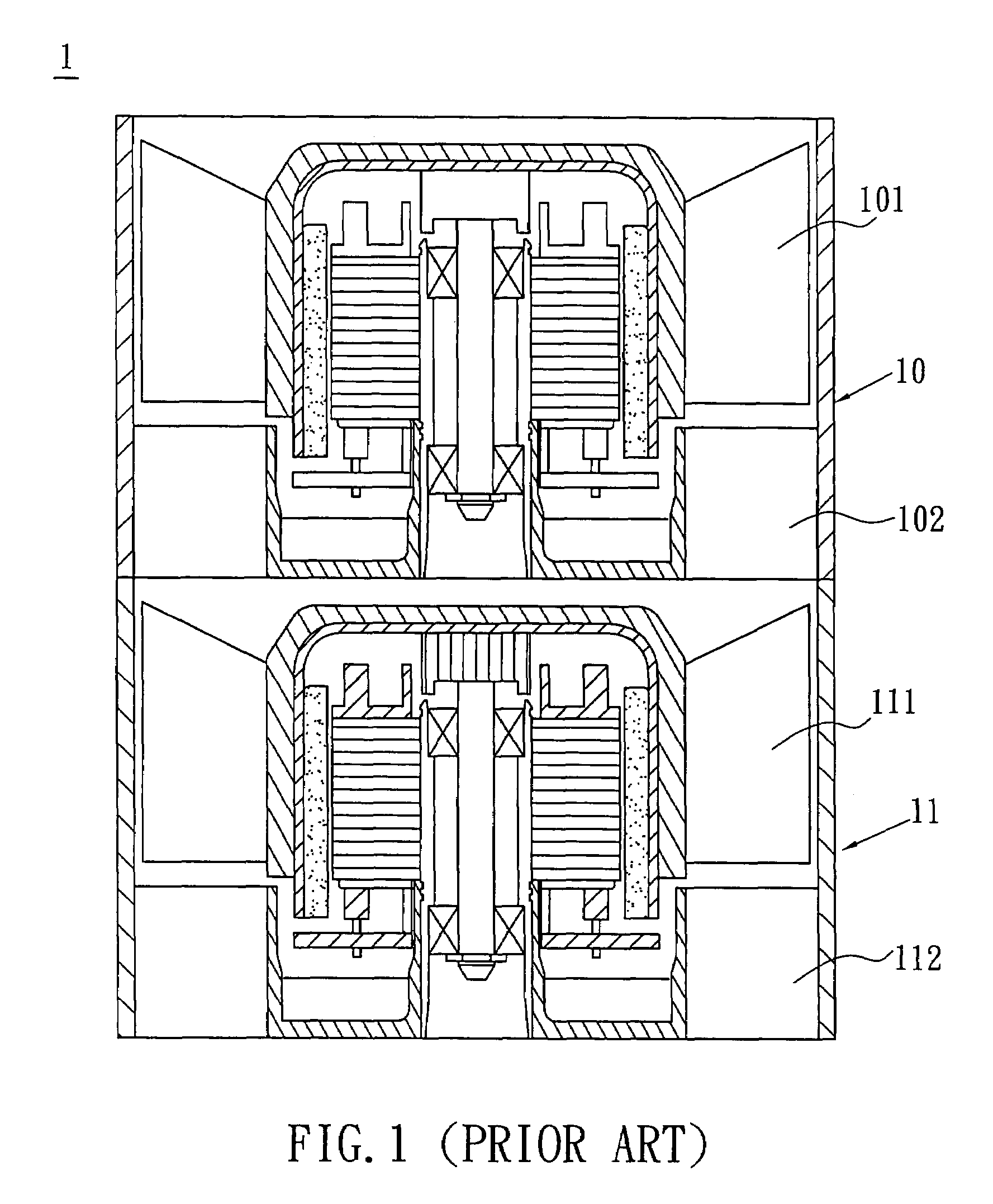
However, for the electronic product that generates lots of heat, only one single fan cannot effectively dissipate the heat energy generated therefrom.
In addition, multiple fans are provided not only to enhance the air volume but also to prevent the situation that only single fan is applied and this fan has a fault so as to interrupt total heat dissipation.
Once the arrangement is poor, no synergy effect is obtained or even the negative effect may occur when the fan and another fan are connected in series.

Method used


Image

  • Serial fan assembly and connection structure thereof
  • Serial fan assembly and connection structure thereof
  • Serial fan assembly and connection structure thereof

Examples


Embodiment Construction

[0020]The present invention will be apparent from the following detailed description, which proceeds with reference to the accompanying drawings, wherein the same references relate to the same elements.

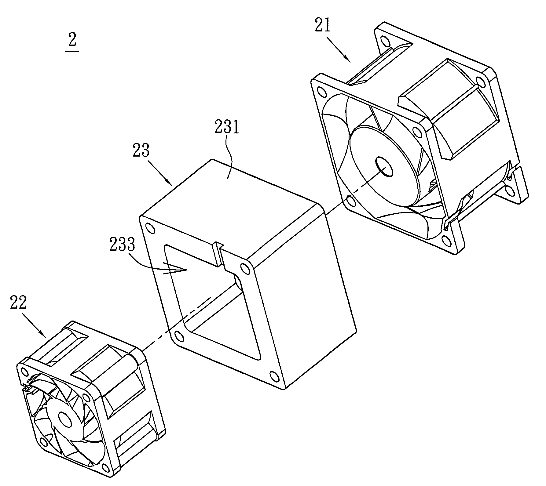
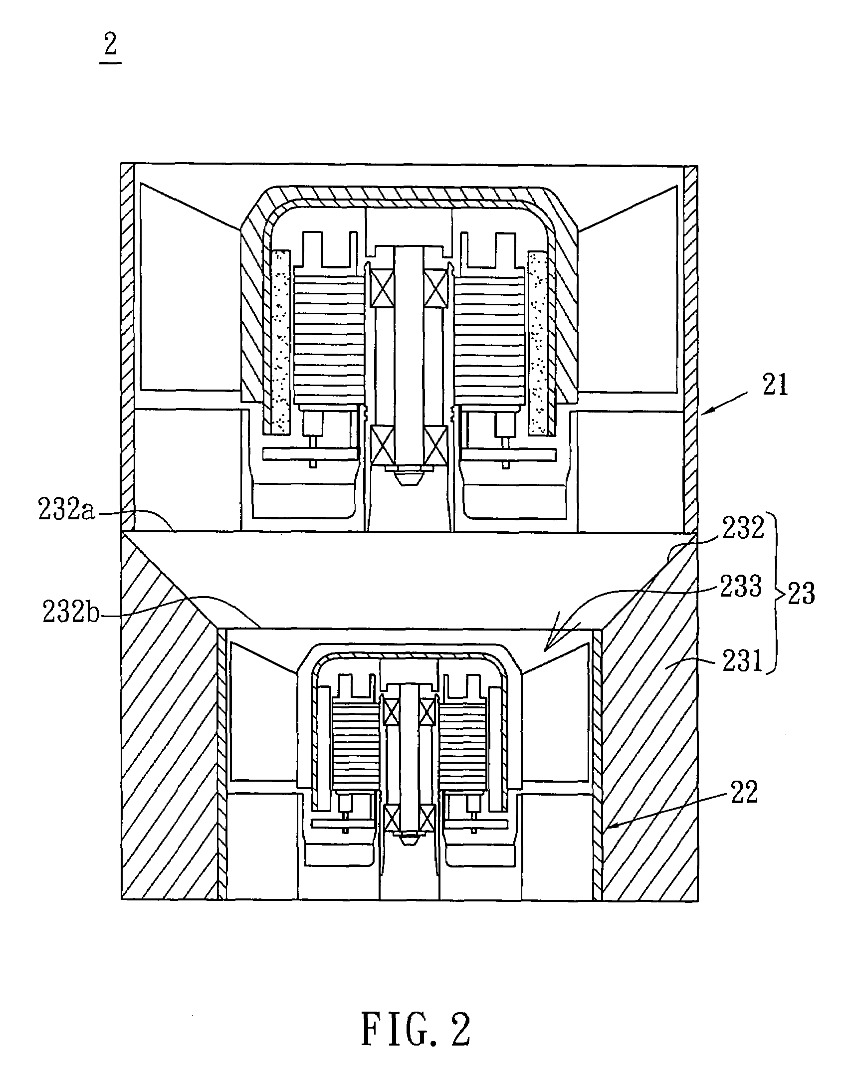
[0021]Referring to FIG. 2, a serial fan assembly 2 according to the preferred embodiment of the present invention includes an upstream fan 21, a downstream fan 22 and a connection structure 23. The upstream fan 21 and the downstream fan 22 may be axial-flow fans.

[0022]The connection structure 23 connects the upstream fan 21 and the downstream fan 22 so that the upstream fan 21 and the downstream fan 22 are arranged in series. In this embodiment, the connection structure 23 and the upstream fan 21 or the downstream fan 22 may be connected with each other by way of engaging, fastening, embedding, adhering, welding, bonding or other ways.

[0023]As shown in FIGS. 2 and 3, the upstream fan 21 and the downstream fan 22 have different sizes. In this embodiment, the size of the upstream fan 21...


PUM


Abstract

A connection structure is applied to a serial fan assembly, which includes an upstream fan and a downstream fan. The upstream fan and the downstream fan have different sizes. The connection structure connects the upstream fan and the downstream fan so that the upstream fan and the downstream fan are arranged in series. The connection structure has a housing, a base and a plurality of ribs for connecting the base, and the housing is formed with an air guiding passage and a chamber. The upstream fan or the downstream fan is accommodated in the chamber or the air guiding passage is located between the upstream fan and the downstream fan.

Description

CROSS REFERENCE TO RELATED APPLICATIONS[0001]This Non-provisional application claims priority under 35 U.S.C. §119(a) on Patent Application No(s). 095143379, filed in Taiwan, Republic of China on Nov. 23, 2006, the entire contents of which are hereby incorporated by reference.BACKGROUND OF THE INVENTION[0002]1. Field of Invention[0003]The present invention relates to a fan and a connection structure thereof. In particular, the present invention relates to a serial fan assembly and a connection structure thereof.[0004]2. Related Art[0005]Electronic products have been rapidly developed toward the properties of high performance, high frequency, high speed, thin thickness and light weight, so the heat generated from the electronic product causes the temperature getting higher and higher during its operation. Thus, high temperature causes unstable phenomenon and further influences the product reliability. Accordingly, the heat dissipation has become one of the important subjects in devel...

Claims


Application Information

Patent Timeline
Patent Type & Authority Patents(United States)
IPC IPC(8): F04D29/52F01P5/04
CPCF04D19/007F04D29/542F04D29/547F04D29/601F04D29/544
Inventor LEE, KUN-MINGHUNG, YA-HUI
Owner DELTA ELECTRONICS INC
Learn More